GE Multilin G60 Generator Protection System 3-51
3 HARDWARE 3.4 FIELD AND STATOR GROUND MODULES
3
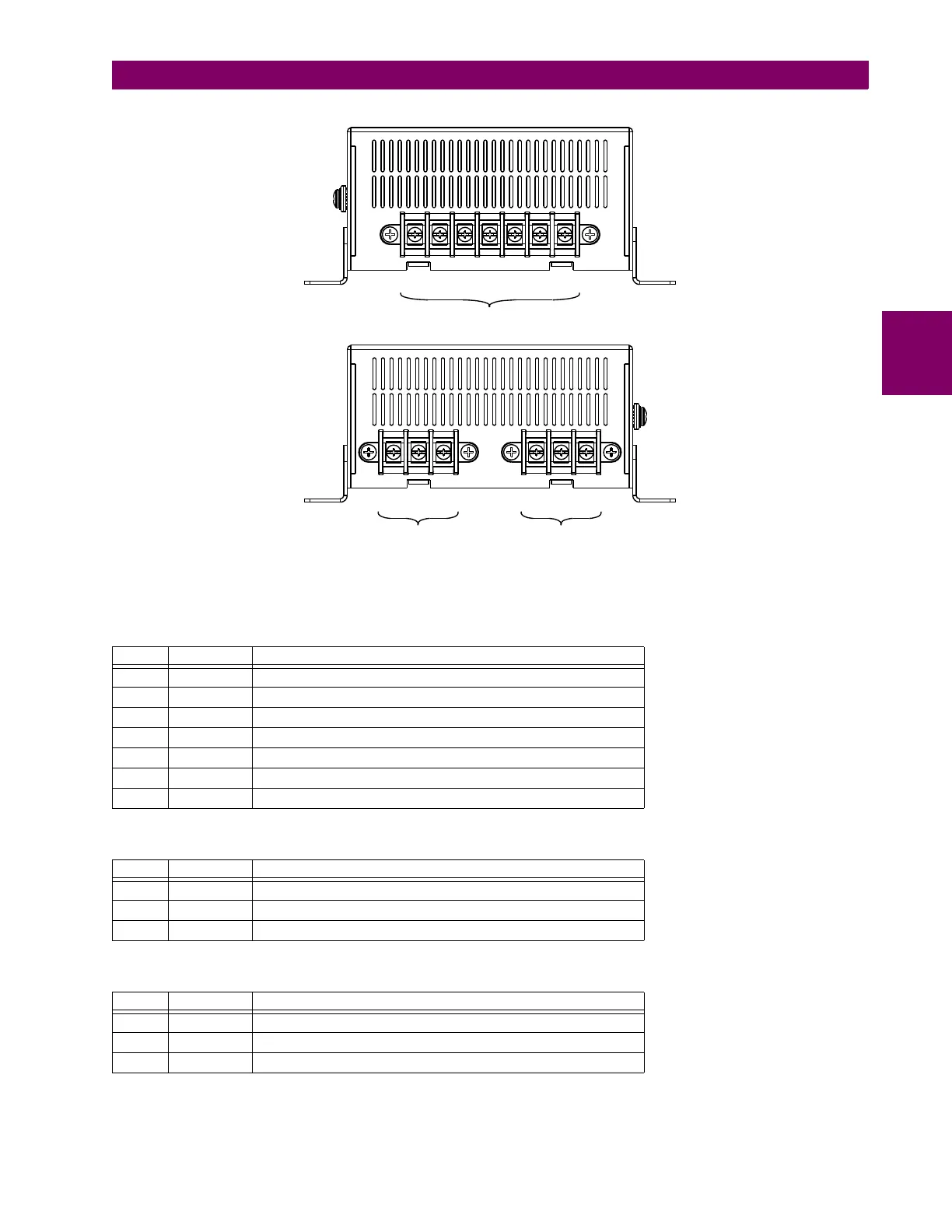
Figure 3–61: GPM-F-R MODULE SHOWING TERMINAL BLOCKS
The pin assignments are described in the following tables.
Table 3–12: GPM-F-R PIN ASSIGNMENTS FOR CONNECTOR A
PIN LABEL DEFINITION
1 A1 Not used
2 A2 Not used
3 A3 Injection secondary (F1)
4 A4 Not used
5 A5 Excitation secondary negative (F–)
6 A6 Not used
7 A7 Excitation secondary positive (F+)
Table 3–13: GPM-F-R PIN ASSIGNMENTS FOR CONNECTOR B
PIN LABEL DEFINITION
1 B1 Excitation primary positive (F2+)
2 B2 Not used
3 B3 Injection to excitation positive (F2)
Table 3–14: GPM-F-R PIN ASSIGNMENTS FOR CONNECTOR C
PIN LABEL DEFINITION
1 C1 Injection to excitation negative / Excitation primary negative (F2–)
2 C2 Not used
3 C3 Not used
&RQQHFWRU$
&RQQHFWRU% &RQQHFWRU&
$&'5

 Loading...


