5-94 G60 Generator Protection System GE Multilin
5.4 SYSTEM SETUP 5 SETTINGS
5
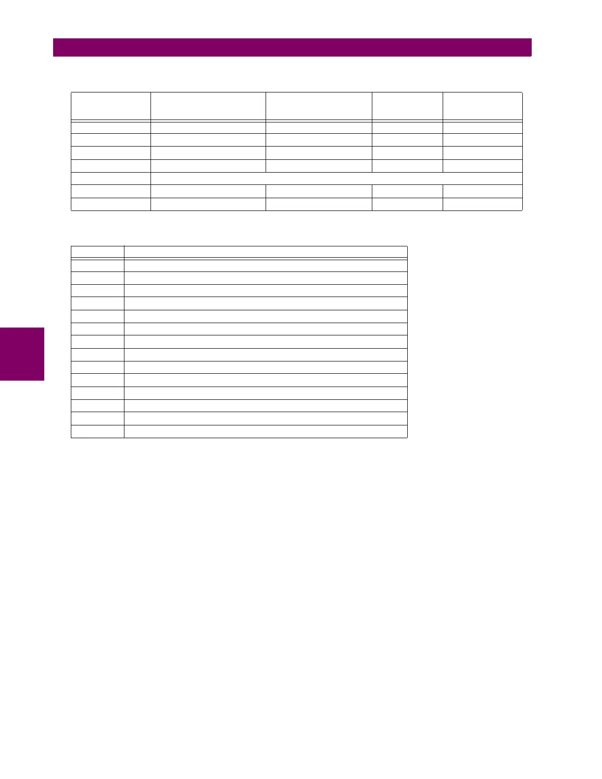
• PMU1 PHS-1 to PMU1 PHS-14: These settings specify synchrophasors to be transmitted from the superset of all syn-
chronized measurements. The available synchrophasor values are tabulated below.
These settings allow for optimizing the frame size and maximizing transmission channel usage, depending on a given
application. Select “Off” to suppress transmission of a given value.
• PMU1 PHS-1 NM to PMU1 PHS-14 NM: These settings allow for custom naming of the synchrophasor channels. Six-
teen-character ASCII strings are allowed as in the CHNAM field of the configuration frame. These names are typically
based on station, bus, or breaker names.
• PMU1 A-CH-1 to PMU1 A-CH-16: These settings specify any analog data measured by the relay to be included as a
user-selectable analog channel of the data frame. Up to eight analog channels can be configured to send any FlexAn-
alog value from the relay. Examples include active and reactive power, per phase or three-phase power, power factor,
temperature via RTD inputs, and THD. The configured analog values are sampled concurrently with the synchrophasor
instant and sent as 16-bit integer values.
• PMU1 A-CH-1 NM to PMU1 A-CH-16 NM: These settings allow for custom naming of the analog channels. Sixteen-
character ASCII strings are allowed as in the CHNAM field of the configuration frame.
• PMU1 D-CH-1 to PMU1 D-CH-16: These settings specify any digital flag measured by the relay to be included as a
user-selectable digital channel of the data frame. Up to sixteen digital channels can be configured to send any Flex-
Logic operand from the relay. The configured digital flags are sampled concurrently with the synchrophasor instant.
These values are mapped into a two-byte integer number, with byte 1 LSB corresponding to the digital channel 1and
byte 2 MSB corresponding to digital channel 16.
• PMU1 D-CH-1 NM to PMU1 D-CH-16 NM: These settings allow for custom naming of the digital channels. Sixteen-
character ASCII strings are allowed as in the CHNAM field of the configuration frame.
• PMU1 D-CH-1 NORMAL STATE to PMU1 D-CH-16 NORMAL STATE: These settings allow for specifying a normal
state for each digital channel. These states are transmitted in configuration frames to the data concentrator.
Table 5–11: PMU REPORT RATE AND DECIMATION FACTOR FOR 50 HZ M-CLASS SYSTEM
PMU REPORT
RATE (USER
SETTING)
FILTERING IN DSP DSP TO CPU
SYNCHROPHASOR DATA
TRANSFER RATE
CPU
DECIMATION
FACTOR
FINAL PMU
STREAM OUTPUT
RATE
50 Hz FIR Filter for 50Hz Rate 50 Hz 1:1 50 Hz
25 Hz FIR Filter for 25Hz Rate 25 Hz 1:1 25 Hz
10 Hz FIR Filter for 10Hz Rate 10 Hz 1:1 10 Hz
5 Hz FIR Filter for 10Hz Rate 10 Hz 2:1 5 Hz
4 Hz The 4 Hz report rate is not allowed in the M-Class 50 Hz system.
2 Hz FIR Filter for 10Hz Rate 10 Hz 5:1 2 Hz
1 Hz FIR Filter for 10Hz Rate 10 Hz 10:1 1 Hz
SELECTION MEANING
Va First voltage channel, either Va or Vab
Vb Second voltage channel, either Vb or Vbc
Vc Third voltage channel, either Vc or Vca
Vx Fourth voltage channel
Ia Phase A current, physical channel or summation as per the source settings
Ib Phase B current, physical channel or summation as per the source settings
Ic Phase C current, physical channel or summation as per the source settings
Ig Fourth current channel, physical or summation as per the source settings
V1 Positive-sequence voltage, referenced to Va
V2 Negative-sequence voltage, referenced to Va
V0 Zero-sequence voltage
I1 Positive-sequence current, referenced to Ia
I2 Negative-sequence current, referenced to Ia
I0 Zero-sequence current

 Loading...


