GE Multilin G60 Generator Protection System B-35
APPENDIX B B.4 MEMORY MAPPING
B
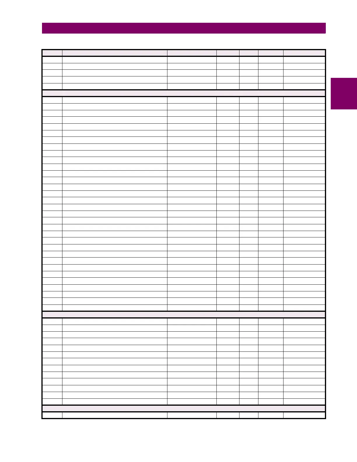
74C8 ...Repeated for dcmA Inputs 20
74E0 ...Repeated for dcmA Inputs 21
74F8 ...Repeated for dcmA Inputs 22
7510 ...Repeated for dcmA Inputs 23
7528 ...Repeated for dcmA Inputs 24
Disconnect switches (read/write settings)
7540 Disconnect switch 1 function 0 to 1 --- 1 F102 0 (Disabled)
7541 Disconnect switch 1 name --- --- --- F206 “SW 1"
7544 Disconnect switch 1 mode 0 to 1 --- 1 F157 0 (3-Pole)
7545 Disconnect switch 1 open 0 to 65535 --- 1 F300 0
7546 Disconnect switch 1 block open 0 to 65535 --- 1 F300 0
7547 Disconnect switch 1 close 0 to 65535 --- 1 F300 0
7548 Disconnect switch 1 block close 0 to 65535 --- 1 F300 0
7549 Disconnect switch 1 phase A / three-pole closed 0 to 65535 --- 1 F300 0
754A Disconnect switch 1 phase A / three-pole opened 0 to 65535 --- 1 F300 0
754B Disconnect switch 1 phase B closed 0 to 65535 --- 1 F300 0
754C Disconnect switch 1 phase B opened 0 to 65535 --- 1 F300 0
754D Disconnect switch 1 phase C closed 0 to 65535 --- 1 F300 0
754E Disconnect switch 1 phase C opened 0 to 65535 --- 1 F300 0
754F Disconnect switch 1 operate time 0 to 65535 s 0.001 F001 70
7550 Disconnect switch 1 alarm delay 0 to 65535 s 0.001 F003 0
7552 Disconnect switch 1 events 0 to 1 --- 1 F102 0 (Disabled)
7553 Reserved (2 items) --- --- --- --- ---
7555 ...Repeated for disconnect switch 2
756A ...Repeated for disconnect switch 3
757F ...Repeated for disconnect switch 4
7594 ...Repeated for disconnect switch 5
75A9 ...Repeated for disconnect switch 6
75BE ...Repeated for disconnect switch 7
75D3 ...Repeated for disconnect switch 8
75E8 ...Repeated for disconnect switch 9
75FD ...Repeated for disconnect switch 10
7612 ...Repeated for disconnect switch 11
7627 ...Repeated for disconnect switch 12
763C ...Repeated for disconnect switch 13
7651 ...Repeated for disconnect switch 14
7666 ...Repeated for disconnect switch 15
767B ...Repeated for disconnect switch 16
Thermal Overload Protecttion (Read/Write Settings)
7738 Thermal Protection 1 Function 0 to 1 --- 1 F102 0 (Disabled)
7739 Thermal Protection 1 Source 0 to 5 --- 1 F167 0 (SRC 1)
773A Thermal Protection 1 Base Current 0.2 to 3 pu 0.01 F001 80
773B Thermal Protection 1 K Factor 1 to 1.2 --- 0.05 F001 110
773C Thermal Protection 1 Trip Time Constant 0 to 1000 min. 1 F001 45
773D Thermal Protection 1 Reset Time Constant 0 to 1000 min. 1 F001 45
773E Thermal Protection 1 Minimum Reset Time 0 to 1000 min. 1 F001 20
773F Thermal Protection 1 Reset 0 to 65535 --- 1 F300 0
7740 Thermal Protection 1 Block 0 to 65535 --- 1 F300 0
7741 Thermal Protection 1 Target 0 to 2 --- 1 F109 0 (Self-reset)
7742 Thermal Protection 1 Events 0 to 1 --- 1 F102 0 (Disabled)
7743 Reserved (2 items) --- --- --- F001 0
7745 Repeated for Thermal Protection 2
Phasor Measurement Unit Power Trigger (Read/Write Setting)
7860 PMU 1 Power Trigger Function 0 to 1 --- 1 F102 0 (Disabled)
Table B–9: MODBUS MEMORY MAP (Sheet 28 of 59)
ADDR REGISTER NAME RANGE UNITS STEP FORMAT DEFAULT

 Loading...


