B-46 G60 Generator Protection System GE Multilin
B.4 MEMORY MAPPING APPENDIX B
B
9BB0 Teleprotection Input 1 States, 1 per register (16 items) 0 to 1 --- 1 F108 0 (Off)
9BC0 Teleprotection Input 2 States, 1 per register (16 items) 0 to 1 --- 1 F108 0 (Off)
VT Fuse Failure (Read/Write Setting) (6 modules)
A09A VT Fuse Failure Function 0 to 1 --- 1 F102 0 (Disabled)
A09B VT Fuse Failure Neutral Wire Open Function 0 to 1 --- 1 F102 0 (Disabled)
A09C VT Fuse Failure Neutral Wire Open 3rd Harmonic Pickup 0 to 3 pu 0.001 F001 100
A041 ...Repeated for module number 2
A042 ...Repeated for module number 3
A043 ...Repeated for module number 4
A044 ...Repeated for module number 5
A045 ...Repeated for module number 6
A0AC VTFF x V0 3rd harmonic 0 to 999999.999 V 0.001 F060 0
Selector switch actual values (read only)
A210 Selector switch 1 position 1 to 7 --- 1 F001 0
A211 Selector switch 2 position 1 to 7 --- 1 F001 1
Selector switch settings (read/write, 2 modules)
A280 Selector 1 Function 0 to 1 --- 1 F102 0 (Disabled)
A281 Selector 1 Range 1 to 7 --- 1 F001 7
A282 Selector 1 Timeout 3 to 60 s 0.1 F001 50
A283 Selector 1 Step Up 0 to 65535 --- 1 F300 0
A284 Selector 1 Step Mode 0 to 1 --- 1 F083 0 (Time-out)
A285 Selector 1 Acknowledge 0 to 65535 --- 1 F300 0
A286 Selector 1 Bit0 0 to 65535 --- 1 F300 0
A287 Selector 1 Bit1 0 to 65535 --- 1 F300 0
A288 Selector 1 Bit2 0 to 65535 --- 1 F300 0
A289 Selector 1 Bit Mode 0 to 1 --- 1 F083 0 (Time-out)
A28A Selector 1 Bit Acknowledge 0 to 65535 --- 1 F300 0
A28B Selector 1 Power Up Mode 0 to 2 --- 1 F084 0 (Restore)
A28C Selector 1 Target 0 to 2 --- 1 F109 0 (Self-reset)
A28D Selector 1 Events 0 to 1 --- 1 F102 0 (Disabled)
A28E Reserved (10 items) --- --- 1 F001 0
A298 ...Repeated for Selector 2
DNP/IEC Points (Read/Write Setting)
A300 DNP/IEC 60870-5-104 Binary Input Points (256 items) 0 to 65535 --- 1 F300 0
A400 DNP/IEC 60870-5-104 Analog Input Points (256 items) 0 to 65535 --- 1 F300 0
Volts Per Hertz (Read/Write Grouped Setting) (2 modules)
A580 Volts Per Hertz 1 Function 0 to 1 --- 1 F102 0 (Disabled)
A581 Volts Per Hertz 1 Source 0 to 5 --- 1 F167 0 (SRC 1)
A582 Volts Per Hertz 1 Pickup 0.8 to 4 pu 0.01 F001 80
A583 Volts Per Hertz 1 Curves 0 to 7 --- 1 F240 0 (Definite Time)
A584 Volts Per Hertz 1 TD Multiplier 0.05 to 600 --- 0.01 F001 100
A585 Volts Per Hertz 1 Block 0 to 65535 --- 1 F300 0
A586 Volts Per Hertz 1 Events 0 to 1 --- 1 F102 0 (Disabled)
A587 Volts Per Hertz 1 Target 0 to 2 --- 1 F109 0 (Self-reset)
A588 Volts Per Hertz 1 T Reset 0 to 1000 s 0.1 F001 10
A589 Volts Per Hertz 1 Voltage Mode 0 to 1 --- 1 F186 0 (Phase-to-Ground)
A58A ...Repeated for Volts Per Hertz 2
Volts Per Hertz Actuals (Read Only) (2 modules)
A5A0 Volts Per Hertz 1 0 to 65.535 pu 0.001 F001 0
A5A1 Volts Per Hertz 2 0 to 65.535 pu 0.001 F001 0
Flexcurves C and D (Read/Write Setting)
A600 FlexCurve C (120 items) 0 to 65535 ms 1 F011 0
A680 FlexCurve D (120 items) 0 to 65535 ms 1 F011 0
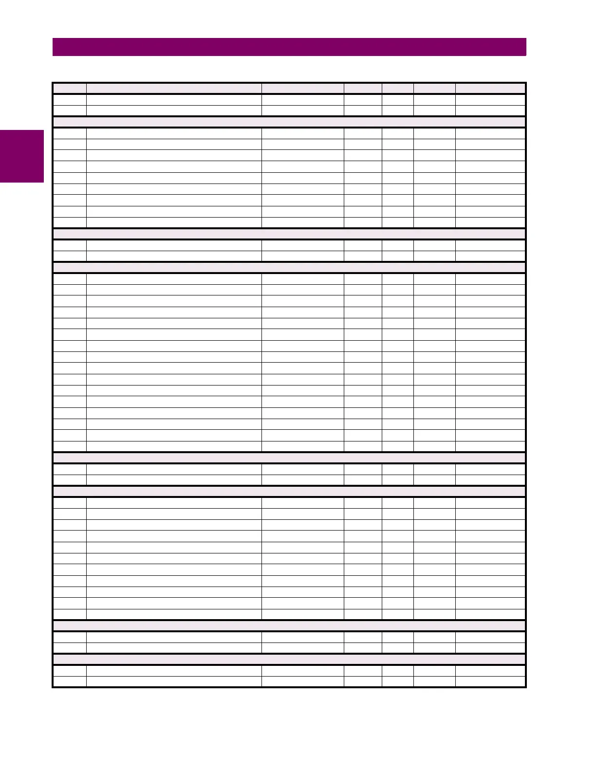
Table B–9: MODBUS MEMORY MAP (Sheet 39 of 59)
ADDR REGISTER NAME RANGE UNITS STEP FORMAT DEFAULT

 Loading...


