2 MM300 MOTOR MANAGEMENT SYSTEM – QUICKSTART GUIDE
MECHANICAL INSTALLATION CHAPTER 2: INSTALLATION
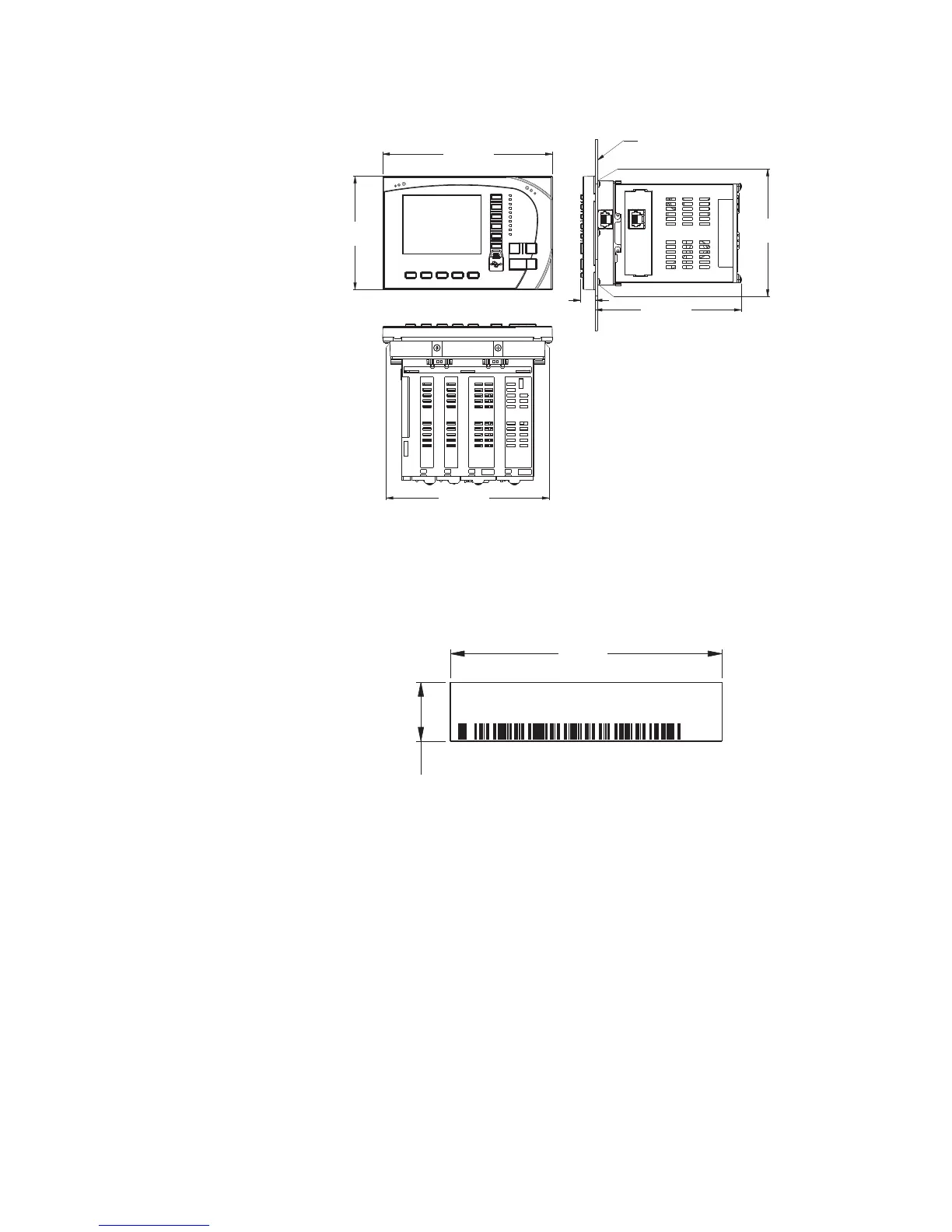
Figure 2-1: MM300 dimensions
Product identification
The product identification label is located on the side panel of the MM300. This label
indicates the product model, serial number, firmware revision, and date of manufacture.
Figure 2-2: MM300 label
Mounting
The MM300 can be mounted three ways: standard panel mount, DIN rail mount, and screw
mount for high vibration environments.
The standard panel mount and cutout dimensions are illustrated below.
6.071”
(154,15 mm)
4.059”
(103,09 mm)
0.565”
(14,35 mm)
5.228”
(132,78 mm)
3.746”
(95,15 mm)
5.550”
(140,97 mm)
853724A1.CDR
PANEL
2.425”
(61.6 mm)
0.525”
(13.3 mm)
853748A1.CDR
Model:
Serial Number:
Firmware:
Mfg. Date:

 Loading...


