8 MM300 MOTOR MANAGEMENT SYSTEM – QUICKSTART GUIDE
ELECTRICAL INSTALLATION CHAPTER 2: INSTALLATION
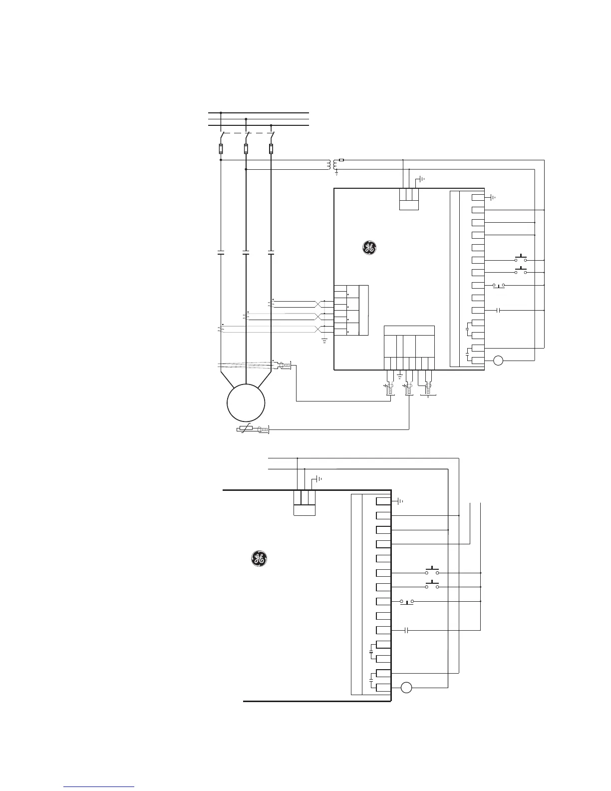
Full-voltage non-reversing starter
Figure 2-10: Full-voltage non-reversing starter wiring - IO_C
Figure 2-11: Full-voltage non-reversing starter control wiring - IO_E
A
B
C
M M M
MOTOR
M
Stator Thermistor
M
Field Stop
Field Start
Reset
Core Balance CT
Contactor
MM300
Low Voltage
Motor
Manager
D2
D1
D8
D7
D6
D5
D4
D3
CT Module
PSU
C1
C2
C3
C4
C5
C6
C7
C8
I/O Module- Type C
C9
C10
C11
C12
C13
C14
I
C
I
B
I
A
Aux VT
+
-
Com
+
CPU
-
R
I
Surge G d
Core
Balance
Thermistor
RS485
CT2
CT3
G/F
CT1
RS485 Serial Link
Ground at one point
N
L
IN 1 IN 2 IN 3 IN 4 IN 5 IN 6 Com
Relay 1 Relay 2
LN
GE Multilin
853704A3.cdr
n
Gd
n
G
M
M
Field Stop
Field Start
Reset
MM300
Low Voltage
Motor
Manager
PSU
C1
C2
C3
C4
C5
C6
C7
C8
I/O Module- Type C
C9
C10
C11
C12
C13
C14
Aux VT
N
L
IN 1 IN 2 IN 3 IN 4 IN 5 IN 6 Com
Relay 1 Relay 2
LN
GE Multilin
853704B3.cdr
Low Voltage
DC Supply to
IO Type E
+
-
AC
Control Power
G

 Loading...


