6 MM300 MOTOR MANAGEMENT SYSTEM – QUICKSTART GUIDE
ELECTRICAL INSTALLATION CHAPTER 2: INSTALLATION
Electrical installation
This section describes the electrical installation of the MM300 system. An overview of the
MM300 terminal connections is shown below.
CAUTION:
MM300 is not to be used in any way other than described in this manual.
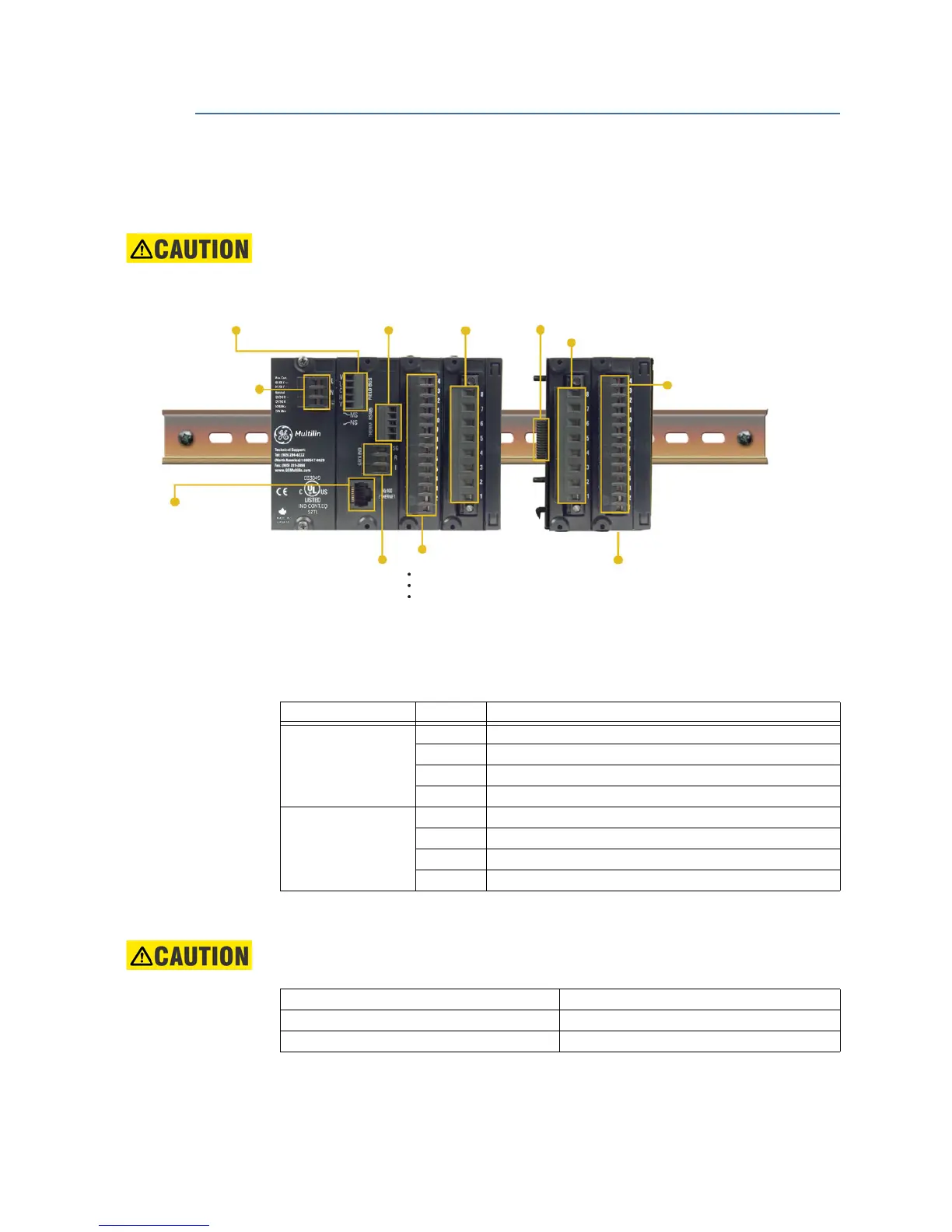
Figure 2-8: MM300 terminal connection overview
The MM300 can contain up to eight modules. The first four modules (slots A through D)
comprise the base unit, and the next four modules (slots E through H) comprise the
optional expanded unit.
Table 2-1: Module slot position
The following figure shows a typical module arrangement for an expanded unit.
CAUTION:
Use gauge size appropriate for the voltage and current draw of the device.
Table 2-2: Gauge Sizes
Expansion module
allows additional digital
inputs/outputs, RTDs, or
voltage inputs
Expansion module
to base unit with a single connector
•
•
•
I/O card includes:
two
contactor outputs
(form
-A)
six programmable inputs
single-phase VT input (60 to 300 V AC)
Optional three-phase
voltage module
RTD Module
with three RTD inputs
Three-phase and
residual ground CT
inputs
Optional TCP/IP
Ethernet
Core-balance ground CT input
RS485 communications
and thermistor input
Profibus or DeviceNet
Optional fieldbus protocols
Switched power supply
allows AC or DC control
voltage
853740A2.CDR
Slot Module types
Base Unit A Power supply module (High or Low)
B CPU module with communications (1 of 3 Comm Types)
C IO_C or IO_E module
D IO_A module
Expansion Modules E IO_B or IO_C or IO_E or IO_D or IO_G module
F IO_C or IO_E or IO_D or IO_G module
G IO_C or IO_E or IO_D or IO_G module
H IO_C or IO_E or IO_D or IO_G module
CPU Card: Themistor, RS485 and Fieldbus 16 AWG (3.50mm pitch terminals)
PSU / CBCT /IO_C / IO_E / IO_D / IO_G 12 AWG (5.00mm pitch terminals)
1
1. Wire gauge size remains constant; increased pitch distance reflects higher voltage rating.
IO_A / IO_B 12 AWG (7.62mm pitch terminals)
1

 Loading...


