20 MM300 MOTOR MANAGEMENT SYSTEM – QUICKSTART GUIDE
INTERFACING WITH THE MM300 CHAPTER 2: INSTALLATION
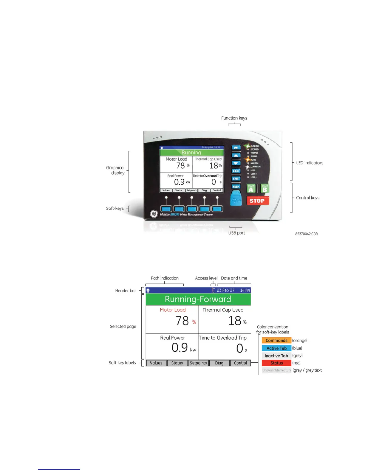
Introduction to the graphical control panel
The central feature of the graphical control panel is a 3.5-inch 320 by 240 pixel backlit
color LCD screen. The panel also contains keys (pushbuttons) that control the display and
perform commands. In addition, the interface contains START A, START B, and STOP direct
acting control pushbuttons.
The display also contains several LED indicators that provide a summary of the machine
status. Details are displayed on the screen when the user navigates to the appropriate
page.
Figure 2-23: MM300 front panel with example default display
Graphical display Each display page consists of the three components shown below.
Figure 2-24: Graphical display overview
The header bar (white text on a blue background) displays the hierarchical path name, the
date and time in 24-hour format, and the current password access level. The hierarchical
path is always displayed on the left top side of the graphical display. The present time is
displayed on the right top side. If the test switch is on, the time is replaced with the text
TEST MODE in red.
The soft-key labels are indicated on the bottom line. The soft-keys are used for navigation,
performing functions, and for acknowledgement.

 Loading...


