12 MM300 MOTOR MANAGEMENT SYSTEM – QUICKSTART GUIDE
ELECTRICAL INSTALLATION CHAPTER 2: INSTALLATION
NOTE:
Change CT wiring only if the system is de-energized!
Figure 2-14: Two CT connection vector diagram
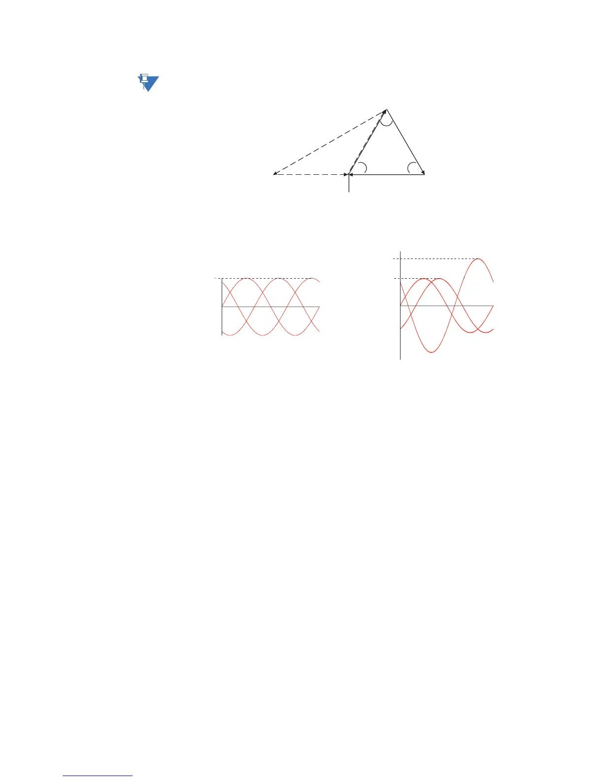
To illustrate the point further, the following diagram shows how the current in phases A
and C sum up to create phase "B".
Figure 2-15: Two CT connection currents
Once again, if the polarity of one of the phases is out by 180°, the magnitude of the
resulting vector on a balanced system will be out by a factor of 1.73.
On a three-wire supply, this configuration will always work and unbalance will be detected
properly. In the event of a single phase, there will always be a large unbalance present at
the interposing CTs of the relay. If for example phase A was lost, phase A would read zero
while phase B and C would both read the magnitude of phase C. If on the other hand,
phase B was lost, at the supply, phase A would be 180° out-of-phase with phase C and the
vector addition would equal zero at phase B.
Phase voltage inputs (IO_B module)
The MM300 has three channels for AC voltage inputs. There are no internal fuses or ground
connections on the voltage inputs. Polarity is critical for correct power measurement and
voltage phase reversal operation.
853715A1.CDR
1.73
11
11
60°
60° 60°
808701A1.CDR
1
C
A
B
1.73
1
B
A
C
Two-phase CT currents
Two-phase CT currents,
180° out-of-phase

 Loading...


