4 MM300 MOTOR MANAGEMENT SYSTEM – QUICKSTART GUIDE
MECHANICAL INSTALLATION CHAPTER 2: INSTALLATION
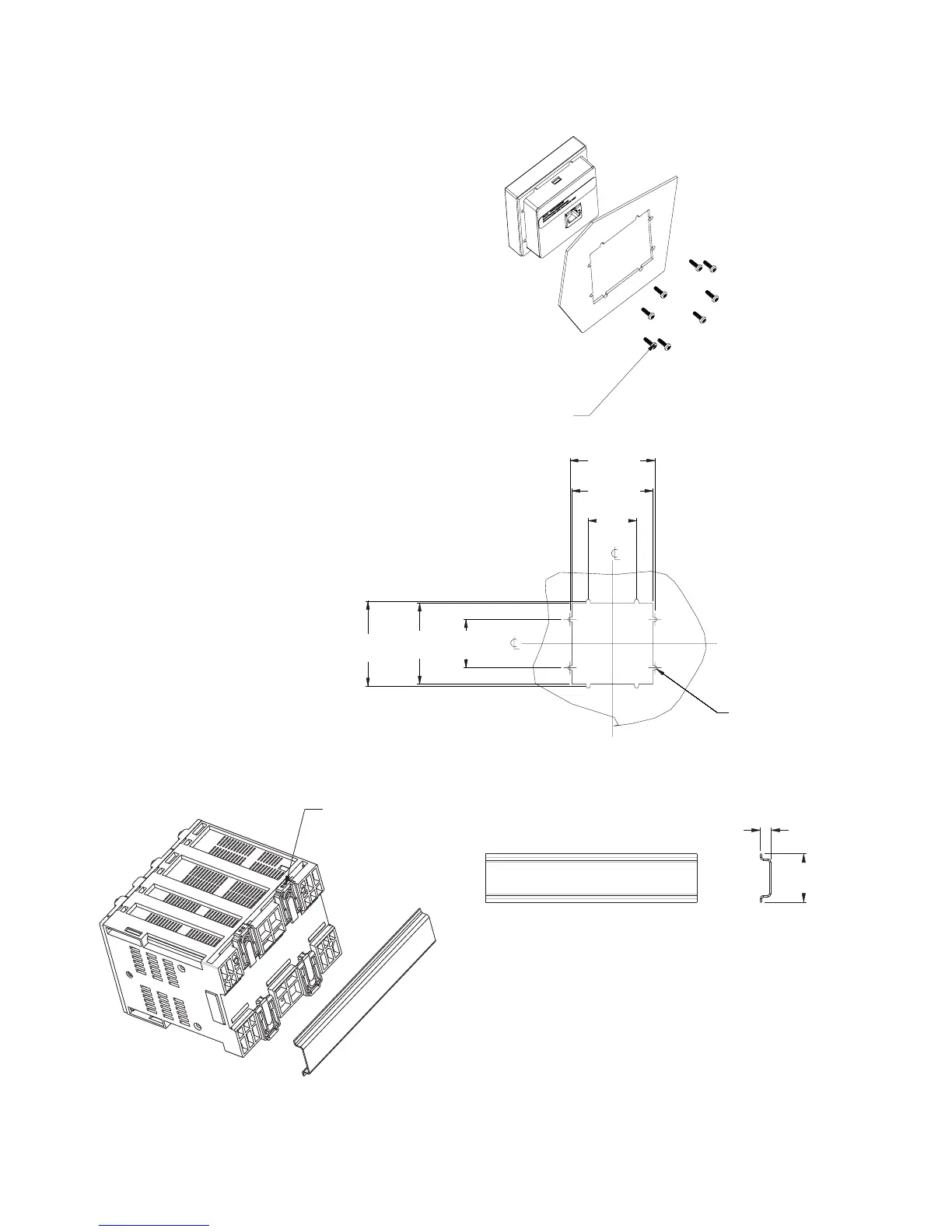
Figure 2-4: Basic Control Panel mounting and cutout dimensions
Figure 2-5: DIN rail mounting - Base and Expansion units
Screw mounts for high vibration environments are illustrated below.
2.515"
63,88mm
[]
2.635"
66,93mm
[]
1.500"
38,10mm
[]
1.500"
38,10mm
[]
2.515"
63,88mm
[]
2.635"
66,93mm
[]
Ø
TypX8
.130"
3,30mm
[]
#4-40X3/8in SELF TAP PAN HD PHILIPS
QTY: 8; (SUPPLIED); GE PART# 1402-0017
TIGHTENING TORQUE: 7 lb-in
.
853825A1.cdr
SNAP-IN THE DIN CLIPS (QTY: 4)
FOR DIN RAIL MOUNTING
0.30”
(7,6 mm)
1.38”
(35,1 mm)
DIN 3 RAIL
853726A1.CDR

 Loading...


