– 39 –
Oven Components
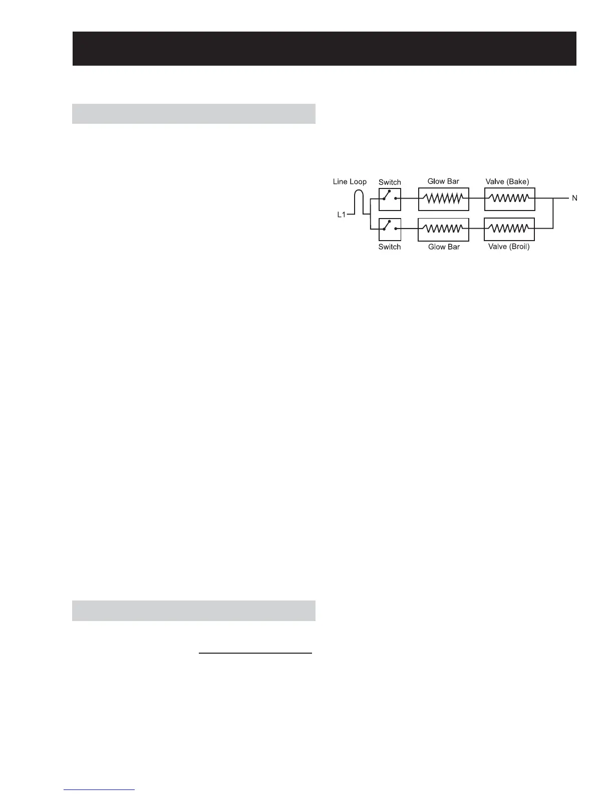
Oven Burner Ignition System
The oven bake and broil burners are ignited by a
glow-bar ignition system. The igniter is a Norton
style rectangular glow-bar. The bake and broil
ignition circuits consist of the electronic control,
an igniter, and an oven safety valve. The three
components are wired in series for each cooking
function.
The most important points to know about the
ignition system are:
• THE IGNITER RESISTANCE DECREASES AS THE
IGNITER SURFACE TEMPERATURE INCREASES.
• THE SAFETY VALVE OPERATES BY CURRENT, NOT
VOLTAGE.
From a cold start, the igniter needs 30 to 60
seconds, with a minimum of 116 volts applied, to
reduce its electrical resistance enough to provide a
minimum of 2.9 amps of current fl ow in the series
circuit. This is the required current fl ow needed
for the safety valve to open and supply gas to the
burner.
The glow-bar should provide a steady current fl ow
of 3.3 to 3.6 amps (3.03 / 3.3 VAC) in the circuit. At
that point, the igniter temperature is 1800°F to
2500°F (982°C to 1371°C). The igniter will remain
energized at all times during burner operation. If
the igniter glows red but does not draw at least 2.9
amps, the fault is usually with the igniter, not the
valve.
Always check the gas shut-off valve on the pressure
regulator for a Not On condition.
Note: If igniter glows, but ignition does not occur, be
sure the gas shut-off valve on the pressure regulator
is in the open position.
Slow ignition can be caused by one or more of the
following conditions:
Blockage of primary air intake: Hole beneath 1.
the bake orifi ce hood must be open and free of
insulation.
Blockage of secondary air intake holes: 2.
Examine oven burner box (galvanized box
surrounding oven burner) and inspect the
single row of secondary holes beneath the
bake burner for signs of blockage. Also, be sure
items in the storage drawer so not push against
the ceiling of the drawer area. If pushed hard
enough, the ceiling will fl ex upward, closing off
the secondary air holes.
Improper alignment of orifi ce hood and burner: 3.
Orifi ce must be pointing straight into burner
venturi.
Improper air/gas adjustment.4.
Blockage of burner crossover slots: Crossover 5.
slots must be open and free of burrs.
Improper installation: Failure to seal all openings 6.
in the wall behind and fl oor below the range
may permit substantial drafts, which can affect
ignition.
The gas control valve should draw 7.
approximately 3.3 to 3.6 amps when operating.
Check by measuring the amperage in L1 to the
oven control. This can be done by removing the
control panel glass and clock/insert assembly.
Glow-bar Igniter
WARNING: This range uses rectangular Norton
glow-bar igniters. They are NOT INTERCHANGEABLE
with cylindrical Carborundum glow-bar igniters. The
two types of glow-bar igniters operate at different
amperage and use different gas valves.
Check the glow-bar circuit with a clamp-on
ammeter. If igniter glows red but circuit does not
draw at least 2.9 amps, the fault is likely with the
igniter, not the valve.
 Loading...