– 40 –
Broil Burner and Glo-bar Igniter
The broil burner glow-bar igniter has an
approximate resistance value of 175 Ω at room
temperature.
The resistance of the broil burner glow-bar igniter
can be checked on the ERC. Place the control panel
in the service position. (See Touch Panel and ERC.)
PGS908 - Test between the BR and N.
PGS968 and PGS975 - Test between the violet wire
on relay RY11 and N.
An open measurement indicates an open igniter,
broil circuit in the control valve, or open wiring.
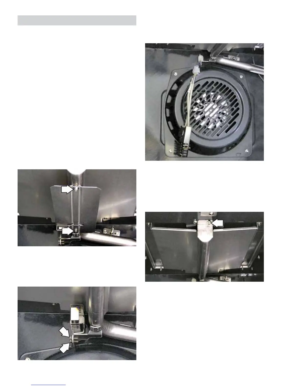
To remove the broil burner and glo-bar igniter:
Remove the oven door. (See 1. Oven Door Removal.)
Remove the two 1/4-in. hex-head screws that 2.
hold the shield to the bottom of the broil burner.
Remove the two 1/4-in. hex-head screws that 3.
attach the glo-bar igniter to the side of the broil
burner.
Gently pull the igniter wiring and harness 4.
through the oven wall, and disconnect the
harness.
Note: Ensure displaced insulation around the wiring
entry hole is returned to it's original position.
Remove the 1/4-in. hex-head screw that holds 5.
the burner in place and remove the burner.
Note: When installing the broil burner, be sure the
orifi ce hood is inserted into the burner inlet opening.
 Loading...