– 50 –
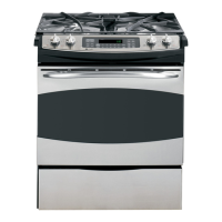
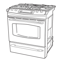
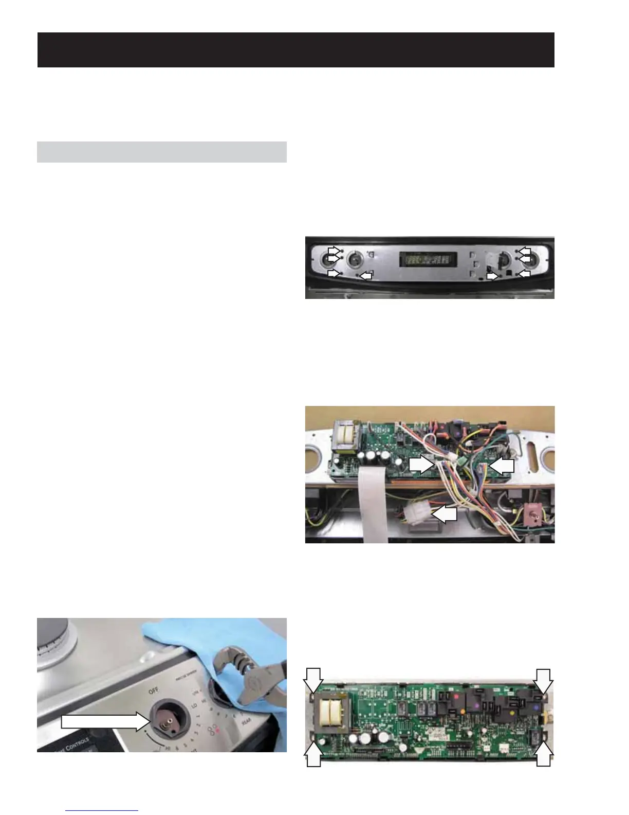
Control Panel Assembly
3. Carefully lift the glass touch panel and
disconnect the ribbon connector.
4. Remove the eight 1/4-in. hex-head screws then
lift the metal insert panel from the control panel
frame.
Touch Panel and ERC
The glass touch panel and ERC are separate
components but must be tested together.
TOUCH PANEL TEST
Press each pad on the touch panel followed by the
start pad. If the touch panel is functioning properly,
the following should occur:
BAKE, BROIL, CONVECTION BAKE (convection •
models), CONVECTION ROAST (convection
models), CLEAN, TIMER, CLOCK, STOP TIME,
COOK TIME, PROOF, PROBE and RANGE
LOCKOUT Modes – Audible tone plus display
showing mode of operation selected.
CLEAR/OFF – Audible tone and display shows •
time of day.
PROBE – Audible tone and response if meat •
probe is plugged in.
Numerical Pads – Audible tone. Can only be •
used after another function has been selected.
To remove the touch panel and ERC:
Disconnect power. 1.
Caution: In the following step, to prevent marring
the fasteners or damaging the glass touch panel, if
using a wrench or pliers, place a towel or cloth over
each fastener.
Remove the knobs. Unscrew and remove the 4 2.
hexagonal control panel fasteners.
WARNING: Components are electrically HOT on control when voltage is connected to range.
The control panel assembly consists of a glass touch panel (keypanel) and an ERC (Electronic Range Control)
that is attached to a metal insert panel.
To replace the ERC it is necessary to disconnect
the ribbon connector, and mark and disconnect the
remaining wiring from the ERC. The ERC is attached
to the metal insert panel with four 1/4-in. hex-head
screws.
5. Position a protective surface over the top of the
range and place the ERC in the service position.
6. Remove the 2 connectors from the ERC and
disconnect the 12-pin wire harness.
Service Position
Fastener (1 of 4)
 Loading...