– 41 –
Bake Burner and Glo-bar Igniter
The bake burner glow-bar igniter has an
approximate resistance value of 105 Ω at room
temperature.
The resistance of the bake burner glow-bar igniter
can be checked on the ERC. Place the control panel
in the service position. (See Touch Panel and ERC.)
PGS908 - Test between the BA and N.
PGS968 and PGS975 - Test between the yellow wire
on relay RY12 and N.
An open measurement indicates an open igniter,
bake circuit in the control valve, or open wiring.
To remove the bake burner and glo-bar igniter:
Remove the oven door. (See 1. Oven Door Removal.)
Remove the range from the installation.2.
Remove the rear cover. (See 3. Rear Cover Removal.)
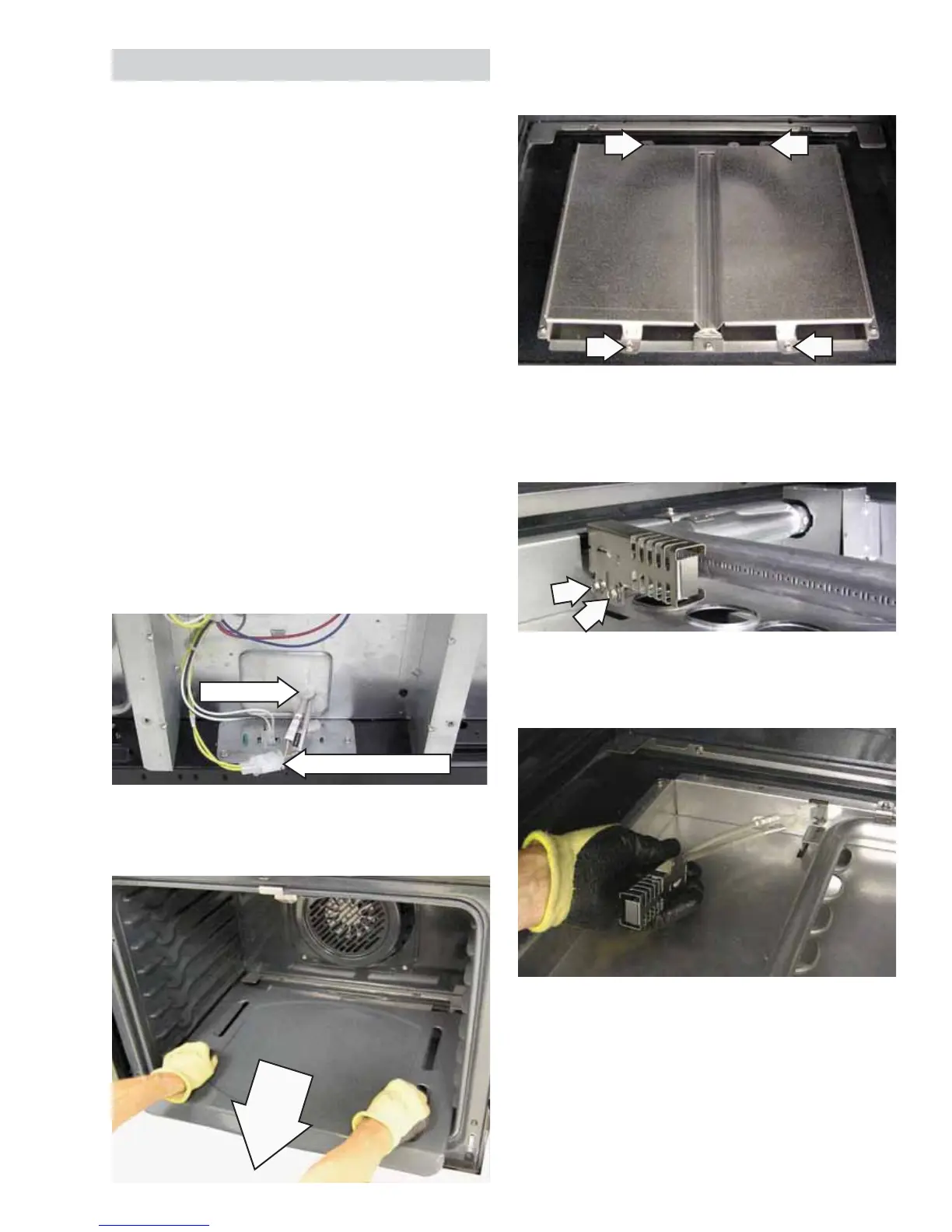
Disconnect the bake igniter wire harness. Note 4.
the location of the igniter wiring entry hole.
Grasp the oven fl oor slots on each side and pull 5.
the fl oor out.
Remove the two 1/4-in. hex-head screws that 7.
attach the glo-bar igniter to the side of the bake
burner.
Remove the four 1/4-in. hex-head screws that 6.
attach the burner baffl e to the bake burner box.
Gently pull the igniter wiring and harness 8.
through the bake burner box.
Note: Ensure displaced insulation around the wiring
entry hole is returned to it's original position.
Igniter Wire Harness
Entry Hole
(Continued next page)
 Loading...