– 59 –
Remove the fi ve 1/4-in. hex-head screws holding 5.
the control panel frame to the maintop baffl e,
then remove the control panel frame.
Maintop Burner Assembly Removal
The maintop, burners, igniters, igniter switch as-
sembly, and manifold and valves, can be removed
as an assembly. Removing the assembly will require
disconnecting the manifold inlet gas tube from the
manifold.
WARNING
Disconnect electrical power to the range •
and turn OFF gas at the main valve before
performing any removal procedures.
Sharp edges may be exposed when servicing. •
Use caution to avoid injury. Wear Kevlar gloves
or equivalent protection.
To remove the Maintop Burner Assembly:
Remove the grates, oven vent cover and cap, 1.
and the 4 burner caps and heads.
Remove the oven vent tower. (See 2.
Maintop Re-
moval.)
Remove the control panel assembly. (See 3.
Control
Panel Assembly.)
Remove the fi ve 1/4-in. hex-head screws from 4.
the top inside edge of the control panel frame.
(Continued next page)
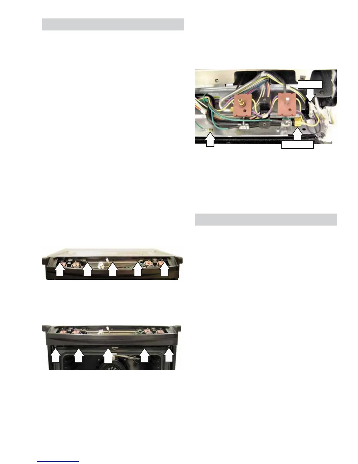
Remove the 1/4-in. hex-head screw that 6.
attaches the ground wire to the burner box and
disconnect the igniter wire harness.
Remove the 11/16-in. nut that connects the 7.
manifold inlet gas tube to the manifold.
Harness
11/16-in. nut
Raise the front of the maintop burner assembly, 8.
slide it to the left. Disconnect the spark module
wire harness. (See Component Locator Views.)
Remove the assembly and place it top-side-9.
down on a protected surface.
Spark Module
The spark module receives line voltage when a
surface burner knob is placed in the LITE position.
The line voltage input to the spark module can be
checked on the ERC.
To test for line voltage to the spark module:
Place the control panel in the service position. 1.
(See Touch Panel and ERC.)
Carefully reinstall the glass touch panel and 2.
connect the ribbon connector.
Connect power to the range. 3.
Lock out the surface burners (See4. Control
Features.) or turn off the gas supply.
With a burner knob turned to the LITE position, 5.
test for line voltage (120 Volts) from the yellow
wire at the switch harness to N (neutral) on the
ERC.
 Loading...