– 56 –
(Continued next page)
Burner Valves
Note: The following describes the procedure to
remove a single burner valve. The procedure to
remove the dual burner valve is similar.
To remove the single burner valve:
Remove the control panel. (See 1.
Touch Panel and
ERC.)
Open the oven door.2.
Remove the fi ve3. 1/4-in. hex-head screws holding
the control panel frame to the maintop baffl e
then remove the control panel frame.
Lift each igniter switch from the burner valve 4.
stem and remove the igniter switch assembly.
Note: The bottom of each switch is molded to
conform to the top of the valve for a locked-in fi t.
For proper igniter operation, each switch must be
locked in to the top of the valve. When installing the
igniter switch assembly, align each switch to the
valve stem and body then push the switch down
fi rmly.
Harness
The switch housings and harness are replaced as
one assembly.
To remove the igniter switch assembly:
Remove the control panel. (See 1. Touch Panel and
ERC.)
Remove the 2 plastic wire ties that hold the 2.
switch harness to the manifold.
Disconnect the igniter switch harness.3.
Igniter Switch Assembly Test
To test the igniter switch assembly, place the control
panel in the service position. (See Touch Panel and
ERC.)
Disconnect the igniter switch assembly harness. On
the switch harness connector check for continuity.
Valve Position Wire Color Continuity
Off Purple to Black 0 Ω
Lite Purple to Black Open
On Purple to Black Open
Off Black to Yellow Open
Lite Black to Yellow 0 Ω
On Black to Yellow Open
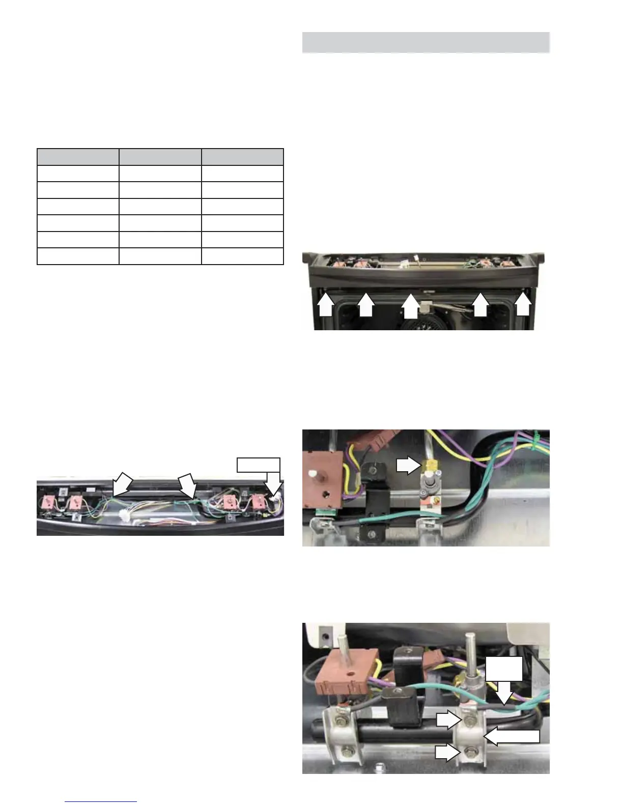
Lift the igniter switch from the burner valve 4.
stem. (See
Igniter Switch Assembly.)
Remove the 9/16-in. nut and separate the 5.
burner tube from the burner valve.
Remove the two 1/4-in. hex-head screws, 6.
ground wire, and bracket that hold the burner
valve to the manifold.
Ground
Wire
Bracket
 Loading...