6. Control Functions and Parameter Settings
6-75
6-7 Adjusting the vector control speed control related parameters
With the VAT2000, ASR operation is possible by executing automatic tuning and setting simple speed
control parameters. However, when carrying out high-response or high-accuracy control, the parameters
must be adjusted in detail. In this section, the configuration and adjustment parameters of the speed
control system is explained.
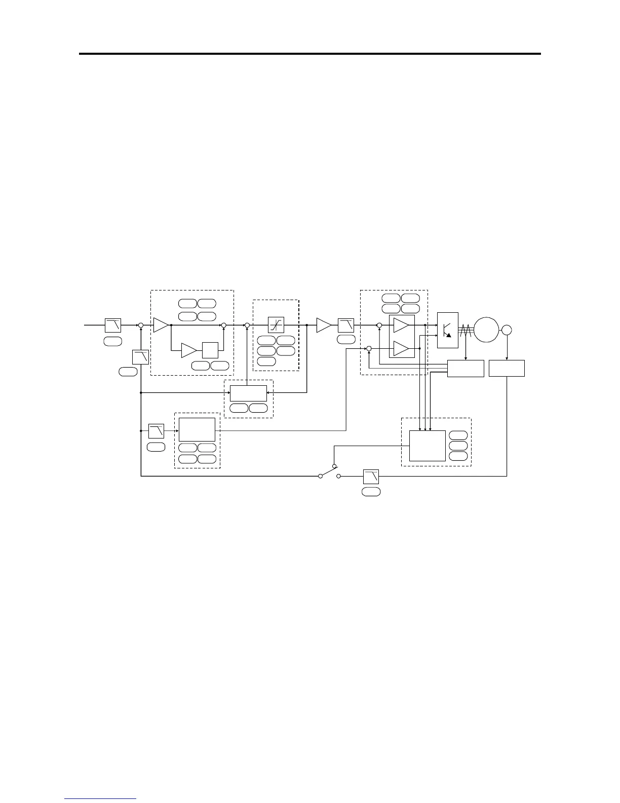
6-7-1 Speed control system for Induction Motors
The speed control system of VAT2000 is configured of blocks as shown below. Automatic tuning is used
for adjusting the exciting current control, current regulator, flux observer and speed estimation
mechanism, so these parameters often do not need to be adjusted. However, the parameters related to
the speed regulator, torque limit, load torque observer, various low path filters, etc., must be adjusted
according to the user's system. Thus, these cannot be simply adjusted with automatic tuning. The final
user of the system must adjust these parameters to match the system. Adjustments are carried out while
referring to the block diagram below.
LPF LPF
LPF
LPF
B30-3
Speed
Setting
B30-5
B30-6
Exciter
Current
Control
A10-0
A30-2
A10-0
ASR
P Control
Gain
Torque
Limiter
I Control
Gain
+
-
A10-2
A30-2
A13-6
A10-3
B31-0
A11-0
B30-0
A10-4
B31-1
A11-1
B32-0
B32-2
A10-5
B31-2
Disturbance
Observer
Torque
Command
A11-2
B13-7
B30-1
B30-7
A11-3
B32-4
Current
Detection
B33-x
B34-x
B30-4
Estimated
Motor Speed
Detected
Motor Speed
Flux
Observer
& Speed
Estimation
Sensorless
Vector Control
Vector Control
with sensor
Motor
Speed
ACR
Speed
Detection
M
PP
LPF
+
+
+
+
+
+
-
-
Torque
Current
VAT2000 speed control system block diagram
(Note) The related parameter Nos. are indicated in the above function blocks.