5. Control Input / Output
5-18
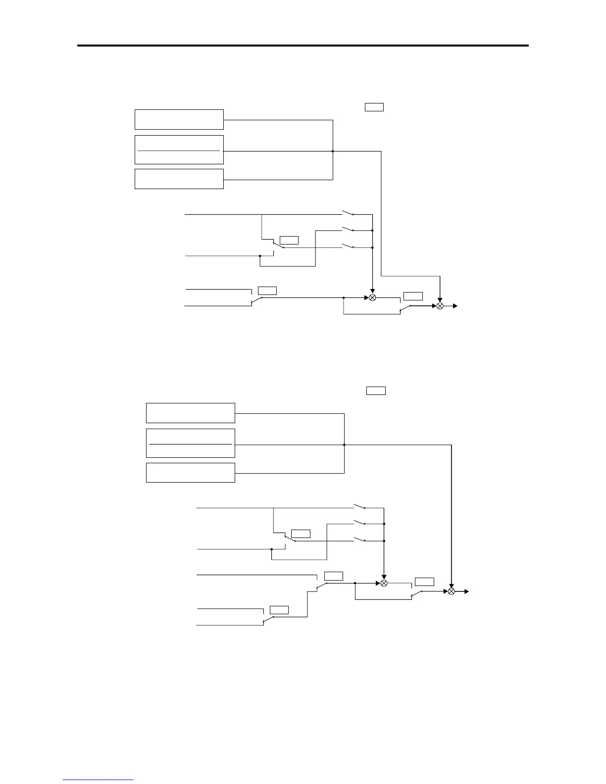
(2) Torque limit setting selection sequence
The interlock sequence for torque limit settings is shown below.
When NFB < NDBL
When NDBL
≤
NFB
≤
NBASE
When NBASE < NFB
:
:
Analog drive torque
limit reduction
setting (C07-7)
Serial drive torque
limit reduction
setting
ACR drive torque
limit (A11-2)
ASR drive torque
limit (A10-3)
KDBL (%)
KDBL (%)
×
NBASE (rpm)
NFB (rpm)
100%
Drive
torque
limiter
on
off
CFS
=1
=2
=3
C02-6
off
on
ACR
off
on
LIM1
XXX
XXX
KDBL
NBF
NBASE
NDBL
: B13-4
Double rating speed ratio (%)
: Speed detection (rpm)
: Base speed (rpm)
: NBASE x KDBL(rpm)
Functions that can be controlled ON / OFF
from terminal board
Functions that can be controlled ON / OFF
By parameter setting only
Fig. 5-12 Drive torque limit setting selection
When NFB < NDBL
When NDBL
≤
NFB
≤
NBASE
When NBASE < NFB
Analog regenerative
torque limit
reduction setting
(C07-8)
Serial regenerative
torque limit
reduction setting
Emergency stop
regenerative torque
limit (A10-5)
ACR regenerative
torque limit (A11-3)
ASR regenerative
torque limit (A10-4)
KDBL (%)
KDBL (%)
×
NBASE (rpm)
NFB (rpm)
100%
Regenerative
side torque
limiter
on
off
CFS
=1
=2
=3
C02-6
off
on
ACR
off
on
LIM2
off
on
EMS
:
:
XXX
XXX
Functions that can be controlled ON / OFF
from terminal board
Functions that can be controlled ON / OFF
By parameter setting only
Fig. 5-13 Regenerative torque limit setting selection