2. Installation and Wiring
2-8
2-4 Precautions for Wiring to the Control Signal
1) Separate the main circuit wiring (to terminals L1, L2, L3, L+1, L+2, L–, B, U, V, W) from the other
drive wires and power wires.
2) Use a 0.25 to 0.75mm² wire for wiring to the control circuit. The tightening torque must be 0.6Nm.
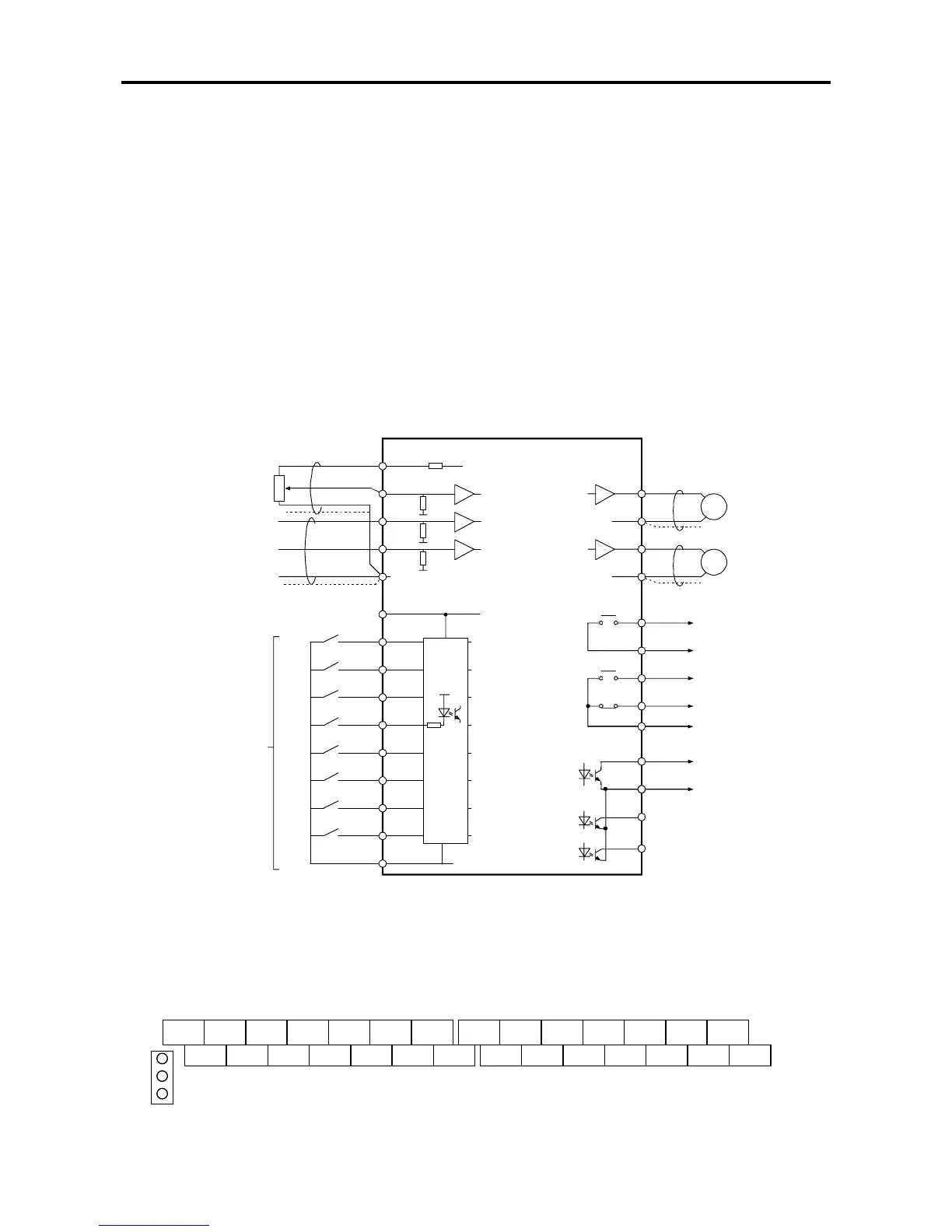
3) Use a twisted pair wire or twisted pair shield wire for wiring the analog signals (as the setters and meter).
(Fig. 2-6.) Connect the shield wire to the TB2 COM terminal of the VAT2000.
The wire length must be 30m or less.
4) The analog output is dedicated for metering only, such as the speed-meter and ammeter.
It cannot be used for control signals such as the feedback control.
5) The length of the sequence input/output contact wire must be 50m or less.
6) The sequence input (digital I/Os), can be selected either sink logic or source logic method by the
short pin (W1). Refer to Table 5-2.
7) Observe the precautions listed in "Table 5-2 Control input/output circuit".
8) An example of the control circuit wiring is given in Fig. 2-6.
9) The layout of the control circuit terminal block is shown in Fig. 2-7; functions are in Table 5-1.
Terminals with the same terminal symbol are internally connected.
10) After wiring, always check the wiring. Do not test control wirings using a megger or buzzer
RESET
COM
AUX
FSI
FSV
P10
20K
+15V
820
Ω
244
Ω
20K
FM
AM
COM
COM
Volta
nal)
RY24
4.7K
F
A
To comply
with UL
use at
30VAC/DC
or lower
PSO2
PSOE
RY24
RY 24V
PSO3
(Notes)
1. Three COM terminals are internally connected.
2. No connection shall be made between RY0 and COM since this section is insulated.
3. This diagram is an example of the sink logic connection. (Refer to Table 5-2.)
Fig. 2-6
• Control terminal
(The terminal block is laid out in two rows.)
TB1 TB2
RY24 RESET PSI1 PSI2 PSI4 PSO1 PSOE PI0 COM AUX AM FM RC FA
RUN EMS RY0 PSI3 PSI5 PSO2 PSO3 FSV FSI COM COM RA FC FB
Fig. 2-7
1
2
3
W1