4. Operation Panel (Keypad)
4-14
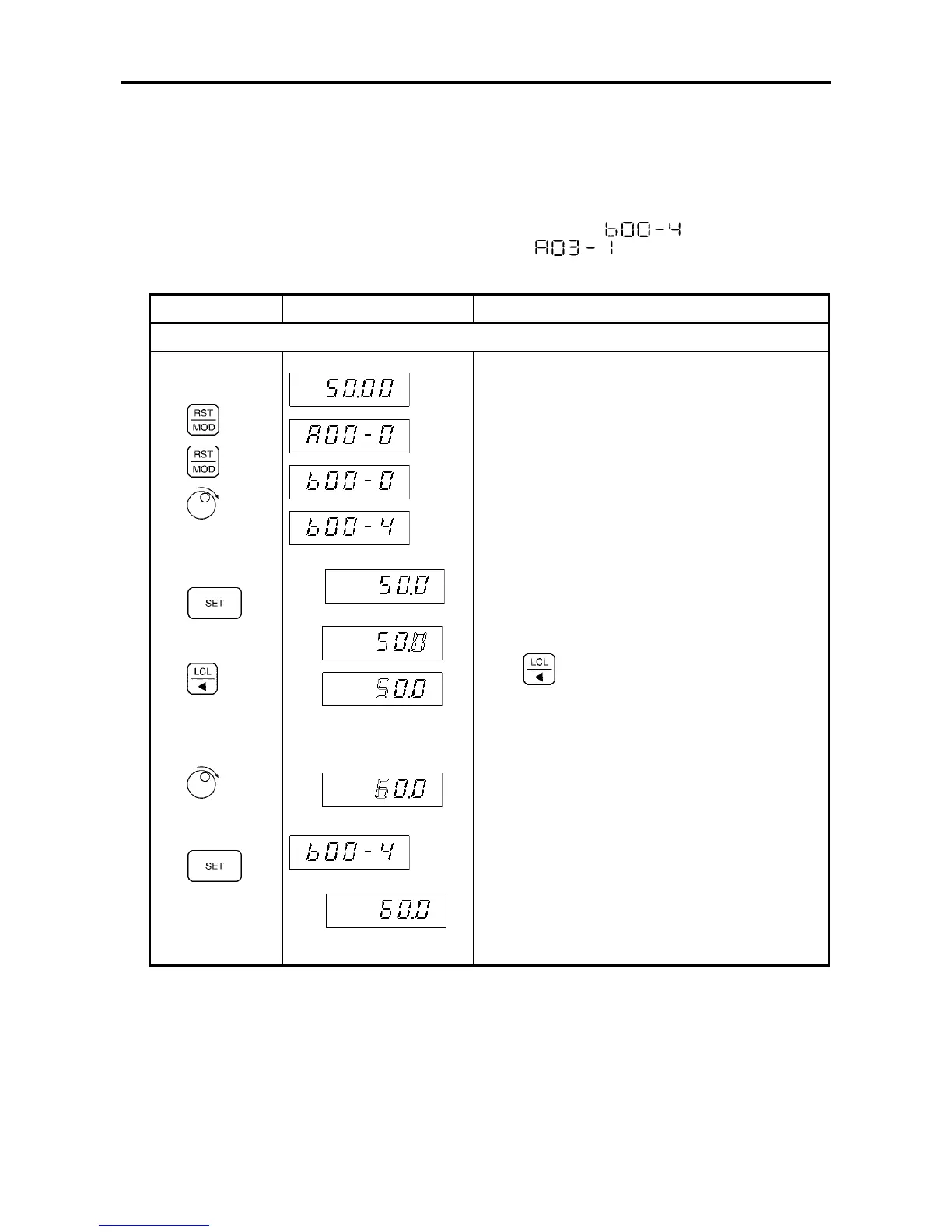
4-5 Reading and adjusting block-A & B & C parameters
1) Refer to Sections 6-2 to 6-5, for the details of the Block-A, B and C parameters.
2) The below shown example is valid if the V/f control (constant torque) is enabled, (C30-0=1).
This example is for changing "maximum output frequency (Fmax) (
)" in Block-B
parameters, and then for changing "DC Breaking Time (
)" in Block-A parameters
Keys Display Explanation
Change the Parameter: B00-4 (maximum output frequency (Fmax) from 50.0 (default value) to 60.0
(1)
(2)
(3)
(4)
(Note 2)
(5)
2 times
(6)
(7)
•
Hz
↓
↑
↓
↑
(In Monitor Mode)
Changes to the Block-A Parameter setting Mode.
Changes to the Block-B Parameter setting Mode.
Increase the parameter No. from parameter B00-0
to B00-4.
The display will alternate between Parameter
Number B00-4 and the present setting value 50.0.
Enable the value to be changed.
The preset setting value will display.
Press
two times to move the flicker to the digit
that is to be changed.
(
Note:
Parameter B00-4 cannot be changed while
the inverter is running.)
Change the flicker digit from 5 to 6.
Fix the data.
The change of Parameter B00-4 to 60.0 will be
completed.
The display will alternate between the Parameter
Number B00-4 and the present value.
(Parameter Number Changing Mode.)