5. Control Input / Output
5-9
5-6 Changing of terminal functions
The programmable input terminals (PSI1 to PSI9) can be arbitrarily assigned to control internal
commands. On the other hand the state of some internal functions can be connected to the
programmable output terminals (RA-RC and PSO1 to PSO5) to lead out the ON/OFF signals.
5-6-1 Sequence input terminal assignment and monitoring
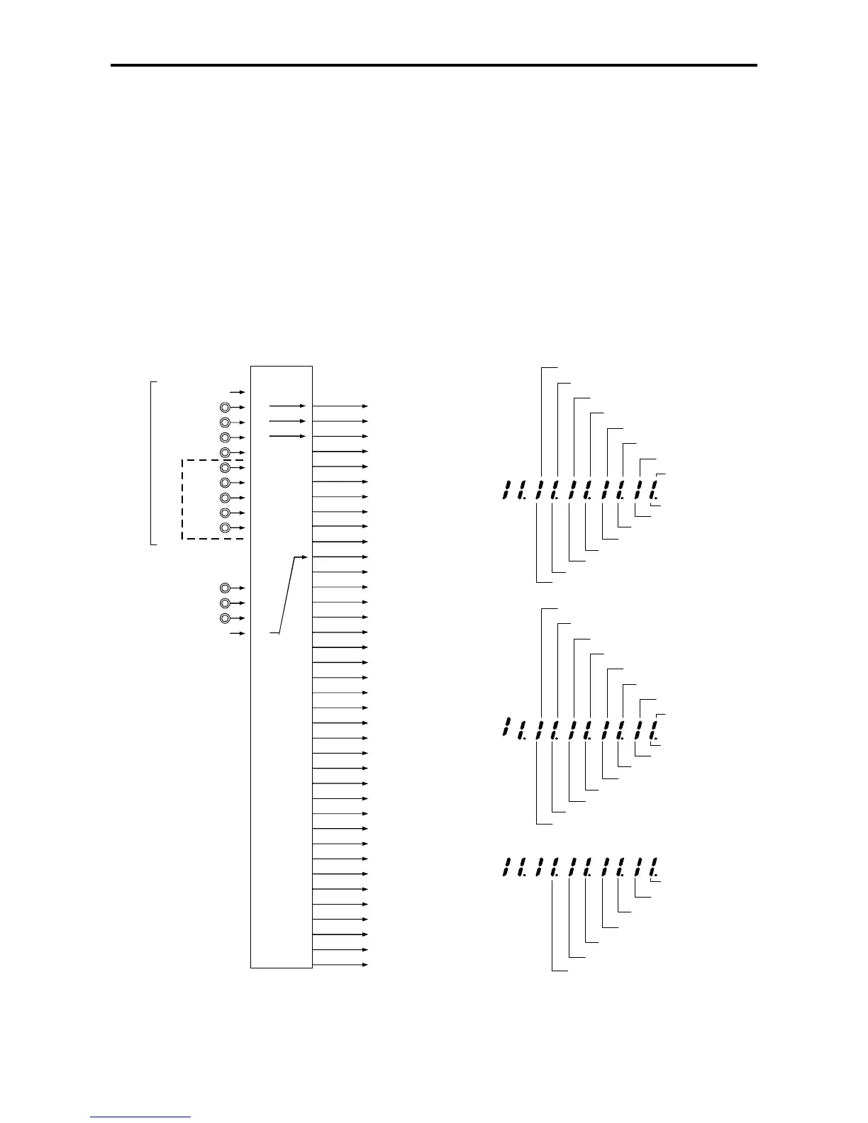
The functions that can be assigned to the terminal block are shown in Fig. 5-3. Each internal function
can be fixed to ON (set value to 16) or OFF (set value to 0). If the function is set for example at “1”,
then input PSI1 can switch that function ON/OFF. Fig 5-3 shows the default assignment, where
R.RUN has been assigned to PSI1 input (C03-0=1).
Fig. 5-4 shows monitoring display allowed by parameter D04-0, 1, or 2. Thus the ON state of each
internal signal can be known trough the operation panel display.
R.RUN
Terminal block Internal command
PSI1
PSI2
PSI3
PSI4
PSI5
PSI6
PSI7
PSI8
PSI9
U2KV23RYO
Option
EMS
F.RUN
ON
1
0
C03-0=1
C03-1=2
C03-2=3
C03-3
C03-4
C03-5
C03-6
C03-7
C03-8
C04-1=16
C 04-2
C04-0
C04-3
C04-4
C04-5
C04-6
C04-7
C04-8
C04-9
C05-0
C05-1
C05-2
C05-3
C05-4
C05-5
C05-6
C05-7
C05-8
C05-9
C06-0
C06-1
C06-2
C06-3
C06-4
C06-5
C06-6
C06-7
C06-8
2
3
4
5
6
7
8
9
10
11
12
13
14
15
16
F.JOG
R.JOG
HOLD
BRAKE
COP
CSEL
IPASS
VFS
CPASS
PIDEN
IFS
AUX
PROG
CSF
S0
S1
S2
S3
SE
FUP
FDW
BUP
BDW
IVLM
AUXDV
PICK
EXC
ACR
PCTL
LIM1
LIM2
MCH
RF0
DROOP
DEDB
TRQB1
TRQB2
Assignement of digital inputs
OFF
PSI
CFS
PROG
AUX
IFS
VFS
CPASS
IPASS
EMS
RESET
RUN
REV
JOG
EXC
BRAKE
D04-0 Display
COP
CSEL
LIM2
LIM1
PCTL
ACR
PICK
AUXDV
IVLM
S0
S1
S2
S3
SE
FUP
FDW
BUP
BDW
MCH
RF0
DROOP
DEDB
TRQB1
TRQB2
PIDEN
D04-1 Display
D04-2 Display
Fig. 5-3 Assignment of sequence input Fig. 5-4 Sequence input monitor