5. Control Input / Output
5-16
5-9-3 Torque bias 1 setting
(1) Torque bias 1 setting selection
A torque bias setting is possible from either analog signals, serial communications or from the
operation panel. All these are selectable by the user.
Setting
input point
Setting data Explanation
Analog Analog torque bias 1
setting
This torque bias setting is possible from an analog input.
Serial
Serial torque bias 1
setting
This torque setting is allowed from a host computer with
serial transmission.
A serial interface option type U2KV23SL0 is required.
Panel Panel torque bias 1
setting
This torque bias setting is allowed by parameter (B13-0).
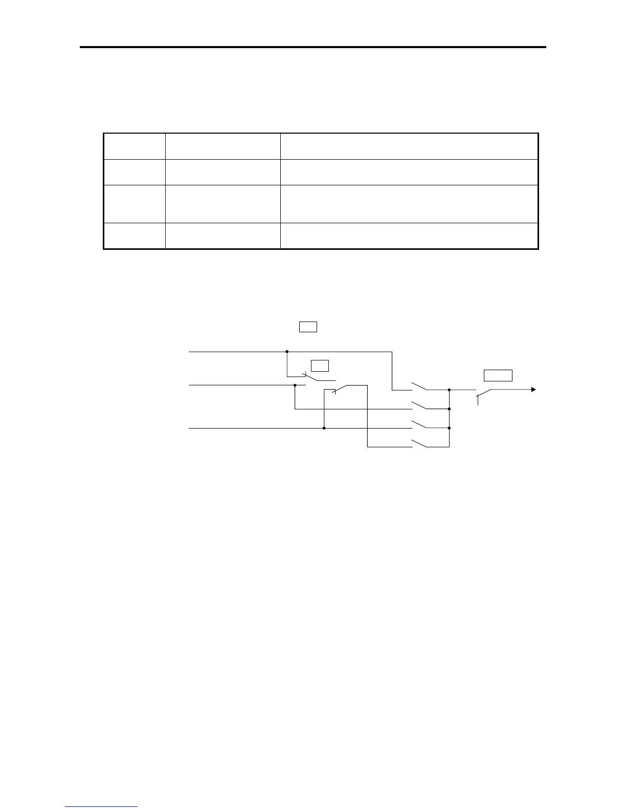
(2) Torque bias 1 setting selection sequence
The relation of the torque bias 1 setting and changeover sequence is shown below.
Analog Torque
bias 1 setting (C07-9)
Serial communication Torque
bias 1 setting
Operation panel
Torque bias 1 setting
(B13-2)
Torque bias 1
setting
LCL
on
off
off
off
on
on
0
C02-4
=1
=2
=3
=4
Functions that can be controlled ON / OFF
from terminal board
XXX
CFS
TRQB1
Fig. 5-11 Torque bias 1 setting selection
5-9-4 Torque limiter function
(1) Torque limit setting selection
The torque limit can be set independently for both speed control (ASR mode) or torque control (ACR
mode) independently for drive or regeneration status. If the VAT2000 is stopped by the emergency
stop signal (EMS), then the regeneration limit is fixed by parameter A10-5.
The parameters used in the torque limiter function are shown below..
A10-3 : ASR drive torque limit setting
A10-4 : ASR regenerative torque limit setting
A10-5 : Emergency stop regenerative torque limit setting
A11-2 : ACR drive torque limit setting
A11-3 : ACR regenerative torque limit setting
The value of above limits can be reduced by external settings. The final limit value results multiplying
the above selected limit with the reduction ratio.