6. Control Functions and Parameter Settings
6-4
Monitor parameters list
ApplicationNo. Parameter Unit Remarks
ST V/f VEC PM
D11 – Torque setting
0 Torque setting % The currently selected torque setting is displayed.
1 Analog torque setting % The setting value from the analog torque input is displayed.
2 Serial communication
torque setting
% The setting value from the serial communication torque input
setting is displayed.
3 Operation panel torque
setting
% The torque set with the operation panel (B13-0) is displayed.
4 ASR output % The ASR output is displayed.
5 Torque setting (after
torque limiter function)
% The forward run direction torque is displayed with the (+)
polarity, and the reverse run direction torque with the (–)
polarity.
D12 – Slip
0 Slip % The slip is displayed as a percentage in respect to the base
speed.
D20 – Extended monitor
0 Fault history reading entry
The last four fault history will display when SET
is pressed.
2 Non-default value
parameter list mode entry
The parameters that differ from the default factory settings are
displayed when key SET
is pressed.
D21 – Maintenance monitor
0 Cumulative Power On
time
Hrs Displays the cumulative power ON time.
1 Cumulative run time Hrs Displays the cumulative run time.
2 CPU version Display the CPU serial number.
3 ROM version Display the ROM serial number.
D22 – Automatic tuning
0 Automatic tuning
progression display
Displays the progression of the automatic tuning.
D30 – Hardware monitor
0 Inverter type This indicates the inverter type
1 Option PCB This indicates the mounted optional PCB.
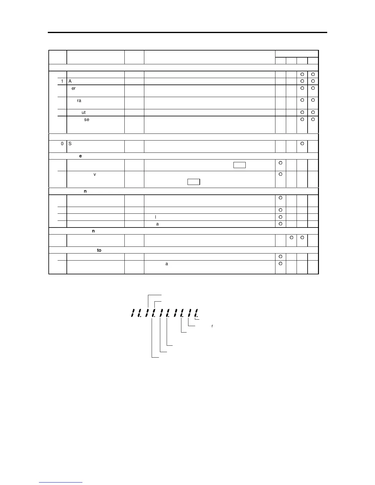
The correspondence of the LED signals is shown below
Relay interface
PC interface
Serial interface
Speed detection 3 (for PM)
Speed detection 1 and 2 (for IM)
Analog interface
Trace Back Interface
Profibus Interface
Option PCB monitor (D30-1
)