6. Control Functions and Parameter Settings
6-6
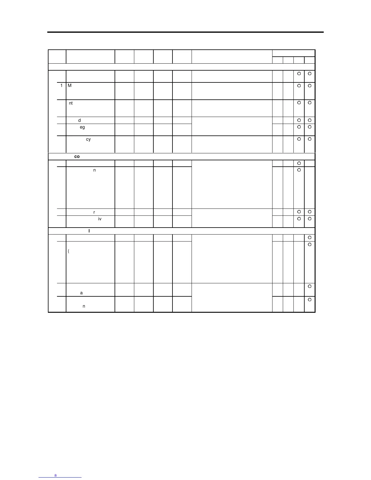
Block-A parameters list
ApplicationNo. Parameter Unit Default Min. Max. Function
ST V/f VEC PM
A10 – ASR control constant 1
0 ASR response rad/s 20.0 1.0 200.0 This is the required ASR response in
radian/sec.
1 Machine time
constant1
ms 1000. 1. 20000. This is the time to accelerate the
motor + load to the base speed at the
motor rated torque.
2 Integral time constant
compensation
coefficient
% 100. 20. 500. This is a compensation coefficient for
the Integral time constant in the
speed regulator.
3 ASR drive torque limit % 100.0 0.1 300.0
4 ASR regenerative
torque limit
% 100.0 0.1 300.0
These are the drive and regenerative
torque limit values for ASR operation.
(Speed Control)
5 Emergency stop
regenerative torque
limit
% 100.0 0.1 300.0 This is the regenerative torque limit
used during the emergency stop
(EMS)
A11 – ACR control constant
0 ACR response rad/s 1000. 100. 6000.
1 ACR time constant ms 20.0 0.1 300.0
The ACR gain and time constant are
set.
This will affect the current response. If
the gain is too low or too high, the
current will become unstable, and the
over current protection will function.
Normally adjust the response
between 500 and 1000, and the time
constant between 5 and 20ms.
2 ACR drive torque limit % 100.0 0.1 300.0
3 ACR regenerative
torque limit
% 100.0 0.1 300.0
Drive and regenerative torque limit
values for ACR operation.
(Torque Control)
A20 – ACR control constant (Permanent Magnet Motors)
0 ACR response (PM) rad/s 1500 100. 6000.
1 ACR time constant
(PM)
ms 10.0 0.1 300.0
These are the gain and time constant
for the current regulator (ACR)
This will affect the current response. If
the gain is too low or too high, the
current will become unstable, and the
VAT2000 may trip by overcurrent .
In general, adjust the response
between 500 and 1000, and the time
constant between 5 and 20ms.
2 d axis current
command ramp time
ms/I1 10.0 0.1 100.0
3 q axis current
command ramp time
ms/I1 10.0 0.1 100.0
This is the ramp setting to prevent
instability caused by overshooting, etc
when current command changes
suddenly.
Set usually a value of 5-10 ms