Installation 2-3
January 2008
Mounting the XDP
System
This section explains how to mount the XDP system components and
the transmitter/sample system at the installation site.
IMPORTANT: The XDP requires an external power disconnect
device such as a switch or circuit breaker. The
disconnect device must be marked as such, clearly
visible, directly accessible, and located within 1.8 m
(6 ft) of the unit.
IMPORTANT: This symbol indicates Caution - risk of electric
shock:
Mounting the XDP
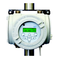
Enclosure
Refer to Figure 2-1 on page 2-9, and complete the following steps to
mount the XDP enclosure:
1. Select a flat surface on a vertical wall or instrument panel with
sufficient space to hold the XDP enclosure.
2. Using the mounting dimensions shown in Figure 2-1 on page 2-9,
locate and prepare four (4) mounting holes or two (2) horizontal
mounting rails on the vertical surface.
3. Secure the XDP enclosure to the mounting surface with four (4)
sets of mounting hardware. Be sure that the enclosure is in a
vertical position, with the display window at the top.
Mounting the Remote
Transmitter/Sample
System
Mount the remote transmitter in accordance with the instructions in
its accompanying documentation.
Note: Most GE Sensing transmitters may be located up to
2,800 ft (850 m) from the XDP enclosure.
To provide reliable and accurate results, the transmitter is often
installed in a suitable sample system. The sample system is designed
to deliver a clean, representative gas sample to the inlet of the
transmitter at the proper temperature, pressure and flow rate.
Note: A suitable sample system may be ordered directly from GE
Sensing. The sample system would be supplied fully assembled
on a flat plate with four (4) mounting holes. See the sample
system and/or transmitter manuals for more details.

 Loading...