80208G_MHW_650-1250-1350_01-2017_ENG
24
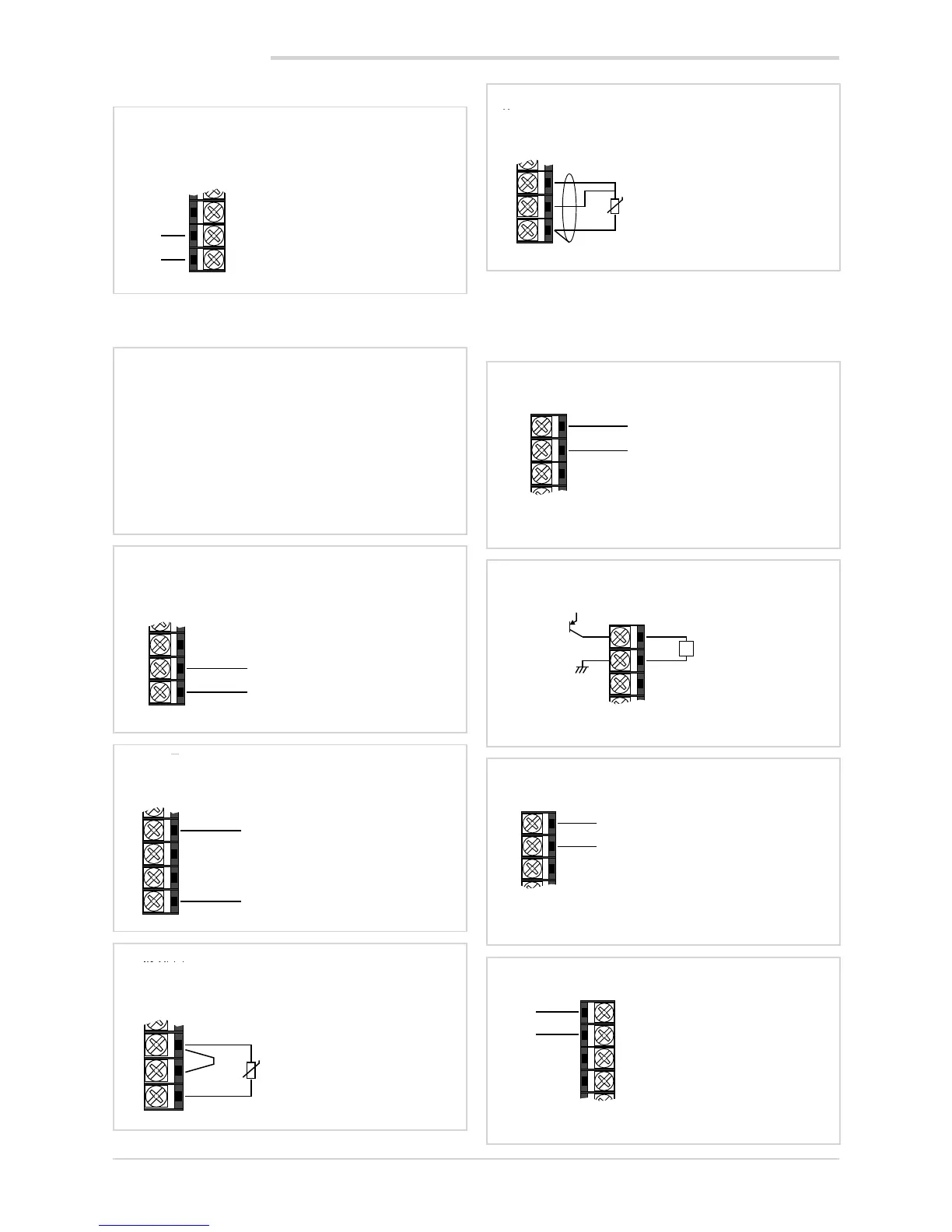
2.3.2. Power supply
2.3.3. Inputs
6
5
4
22
23
24
~
~
PWR
Power supply
Standard: 100...240 VAC/VDC ±10%
50/60Hz, max 5 VA
Optional: 20...27 VAC/VDC ±10%
50/60Hz, max 5 VA
6
5
2.3.4. Outputs
Characteristics of outputs are defined when the controller is
ordered.
4
6
5
Output Out 1 – logic
Logic 24 V
(10 V to 20 mA)
+
-
L
+V
6
5
4
3
2
Output Out 1 – continuous
4...20 mA continuous
Rout < 500 Ω
+
-
2. INSTALLATION
5
4
3
2
1
Linear input (V, I)
Linear input in direct current
0/4...20 mA, Ri = 50 Ω
+
-
Linear input voltage
60 mV (Ri > 70 kΩ)
1 V (Ri > 15 kΩ)
65
4
3
2
1
+
-
Linear input (V)
Linear input in direct voltage
5V, 10 V (Ri > 30 kΩ)
6
5
4
3
2
Output Out 1 – 5 A relay
5 A Relay
250 VAC
NO
C
19
20
21
22
23
24
NO
C
Output Out 2 - 5 A relay
5 A Relay
250 VAC
Attention:
with this type of connection the
line resistance can introduce me-
asurement error, we recommend
that you use wires of adequate
screen.
The resistance of the three wires
must be equal, the line resistance
must be less than 20 ohm.
5
4
3
2
1
T
Input PT100/JPT100 - 3-wires connection
Attention:
with this type of connection the line
resistance can introduce measure-
ment error, we recommend that
you use wires of adequate.
5
4
3
2
1
T
Input PT100/JPT100 - 2-wires connection