25
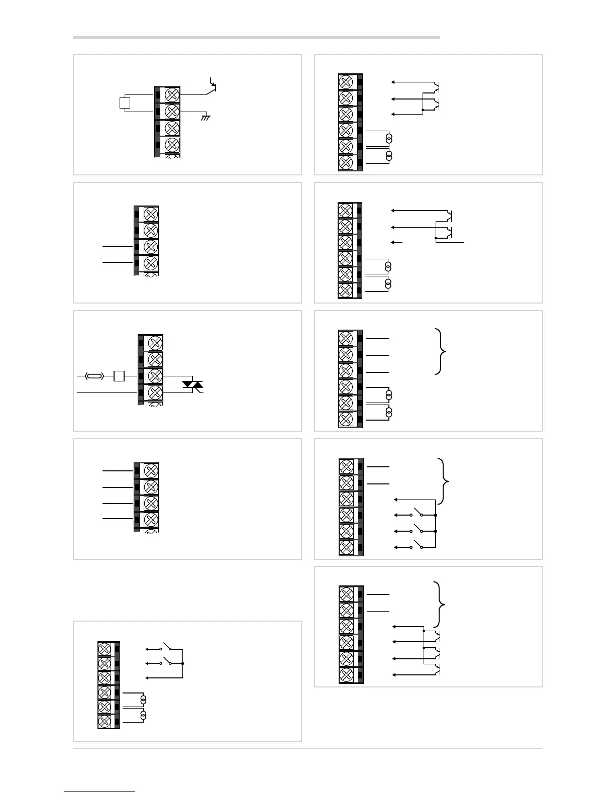
2.3.5. Options
Characteristics of optional inputs and outputs are defined
when the controller is ordered.
21
22
19
20
Output Out 2 – logic
Logic 24 V
(10 V to 20 mA)
+
-
L
+V
19
20
21
22
23
24
NO
C
Output Out 3 – 5 A relay
5 A Relay
250 VAC
19
20
21
22
Output Out 3 – Triac
Triac 75...264 VAC
max 1 A
~
~
L
Fuse
19
20
21
22
23
24
NO 4
NO 3
NO 2
C
Output Out 4 – 5 A relay
5 A relay 250 VAC / 30 VDC
Ic max = 5 A
7
8
9
10
11
12
Option 1
Current transformer
50 mA, 10 Ω, 50/60 Hz
Digital inputs voltage-free contact
Second current transformer for
2-phase / 3-phase load
COM
IN1
IN2
CT1
CT2
~
~
~
7
8
9
10
11
12
Option 1
Current transformer
50 mA, 10 Ω, 50/60 Hz
Digital inputs
NPN 24 V, 4,5 mA
Second current transformer
for 2-phase / 3-phase load
COM
IN1
IN2
CT1
CT2
~
~
~
7
8
9
10
11
12
Option 1
Current transformer
50 mA, 10 Ω, 50/60 Hz
PNP digital inputs
+12/24 V max 3,6 mA
Second current transformer
for 2-phase / 3-phase load
COM
IN1
IN2
CT1
CT2
~
~
~
GND
7
8
9
10
11
12
Option 2
Current transformer
50 mAac, 10 ohm, 50/60 Hz
Serial line
RS485 2-wires
Second current transformer
for 2-phase / 3-phase load
A (Data -)
B (Data +)
CT1
CT2
~
~
~
COM
7
8
9
10
11
12
Option 3
Serial line
RS485 2-wires
A (Data -)
COM
IN3
IN2
IN1
B (Data +)
Digital inputs
voltage-free contact
7
8
9
10
11
12
Option 3
Isolated serial line
RS485 2-wires
B (Data -)
COM
IN3
IN2
IN1
A (Data +)
Digital inputs
NPN 24 V, 4,5 mA
2. INSTALLATION