68 ADV200 • Functions description and parameters list
Menu PAR Description UM Type FB BIT Def Min Max Acc Mod
14.34 1602 Analog inp 1X type ENUM -10V..+10V 0 6 RW FVS
14.46 1652 Analog inp 2X type ENUM -10V..+10V 0 6 RW FVS
Selection of the type of expansion card input (voltage or current input). Depending on the input signal, move
the switches on the expansion card. Standard inputs are coded for voltage signals.
0 -10V…+10V
1 0..10V
2 4..20mA
3 0..20mA
4 PT1000
5 NI1000
6 PT100
7 0.1V..10.1V
8 KTY84
Select option 0 in order to connect a maximum voltage of ±12.5V (typically ±10V/5mA) to the analog input con-
cerned. If the signal is used as a reference, reverse the direction of rotation of the drive by inverting the voltage
polarity.
Select option 1 to connect a max voltage of 12.5V (typically 10V/5mA).
Select option 2 to connect a current signal of 4...20 mA to the analog input concerned. The signal must be positive.
Select option 3 to connect a current signal of 0...20 mA to the analog input concerned. The signal must be positive.
Select option 4 to connect a signal from a PT1000 probe to the analog input concerned.
Select option 5 to connect a signal from an NI1000 probe to the analog input concerned.
Select option 6 to connect a signal from a PT1000 probe to the analog input concerned.
Select option 7 to connect 0.1V...10.1V to the analog input in use. You can also detect signal loss (due to dis-
connection or short circuit) with alarm [62] AnalogInpLoss.
Select option 8 to connect a KTY84 temperature sensor to the analog input in use (you have to use an analog
output as power supply signal). You can also detect signal loss (due to disconnection or short circuit) with
alarm [62] AnalogInpLoss.
Menu PAR Description UM Type FB BIT Def Min Max Acc Mod
14.35 1604 Analog inp 1X scale FLOAT 1.0 -20.0 20.0 RW FVS
14.47 1654 Analog inp 2X scale FLOAT 1.0 -20.0 20.0 RW FVS
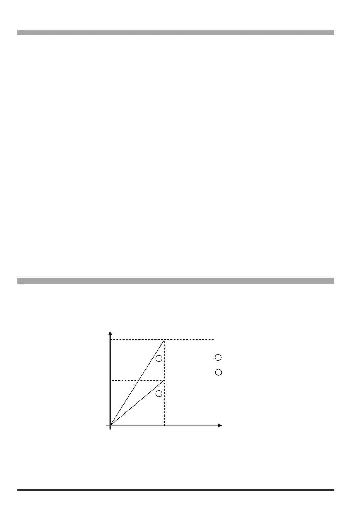
Setting of a multiplier factor to apply to the relative analog input of the expansion card.
1
2
1
2
Analog inpxX scale = 1,0
Analog inp xX scale = 2,0
0
100%
50%
Speed
Example:
The speed reference of a drive is assigned with a max external voltage of 5V. With this value the drive must
reach the maximum speed allowed (set using Full scale speed).
As the Analog inp X scale parameter the scale factor of 2 is entered (10V : 5V)