EasyManua.ls Logo

gefran VDL200 Series User Manual

gefran VDL200 Series
66 pages
To Next Page IconTo Next Page
Page #1 background imageLoading...
Page #1 background image
.... Quick start up guide
Specification and installation
SIEIDrive
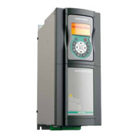
Vector inverter for lifts with
asynchronous motors
VDL200

Table of Contents

Other manuals for gefran VDL200 Series

Questions and Answers:

gefran VDL200 Series Specifications

General IconGeneral
CategoryDC Drives
Output CurrentUp to 200A
FeedbackTachometer, Encoder
CommunicationProfibus, CANopen
ProtectionOvercurrent, Overvoltage, Overtemperature
Operating Temperature0°C to 40°C
Storage Temperature-20°C to 70°C
Humidity5% to 95% non-condensing

Summary

Information about this manual

Software version

Manual update status based on software versions.

General information

General notes on terms, safety, and product modifications.

Safety Precautions

Symbols used in the manual

Explanation of symbols used for warnings and important notes.

Safety precaution

General safety instructions for handling electrical drives.

General warnings

Warnings about dangerous voltages, mechanical parts, and electrical hazards.

Disclaimer

Limitation of liability and usage conditions.

Introduction to the product

Dedicated features

Specific features of the VDL200 for lift applications.

Other features

Additional functionalities and characteristics of the VDL200 drive.

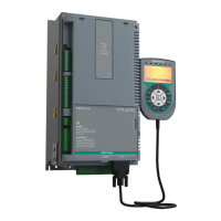
Identification of components

Diagram and explanation of the inverter's functional blocks.

Product identification

Details on product code, data plate, and model naming conventions.

Transport and storage

General

Guidelines for careful handling, packing, and unpacking of the drive.

Permissible Environmental Conditions

Specifies temperature, humidity, and air pressure limits for storage and transport.

Specification

Environmental Conditions

Details installation location, altitude, operating temperature, and air humidity.

Standards

Lists applicable standards for climatic conditions, safety, EMC, and approvals.

Precision

Details performance specifications for speed and torque.

Input electrical data

Tables for input voltage, frequency, and current for different sizes.

Output electrical data

Details output specifications and derating factors.

Voltage level of the inverter for safe operations

Specifies the minimum waiting time before internal operation after power-off.

No-load consumption (Energy rating)

Table showing stand-by and fan consumption for different drive sizes.

Cooling

Details heat dissipation, fan capacity, and cabinet opening requirements.

Weights and dimensions

Provides physical dimensions and weight for different drive sizes.

Options

Optional external fuses

Lists recommended fuses for network side protection.

Input chokes

Explains the benefits and types of input chokes.

AC output chokes

Recommends AC output chokes for standard motors and long cable runs.

External braking resistors (optional)

Lists recommended external braking resistors and their technical data.

EMC Filter (optional)

Details optional external EMC filters, their specifications, and compliance.

Mechanical installation

Maximum inclination and assembly clearances

Specifies mounting angle and clearance requirements for airflow.

Fastening positions

Illustrates mounting hole positions and screw recommendations.

Wiring Procedure

Power section

Instructions for connecting the power components of the drive.

Regulation section

Instructions for connecting control and feedback signals.

Connection diagrams

Wiring diagrams for typical configurations and emergency setup.

Serial interface (PC connector)

Drive/RS232 port point-to-point connection

Instructions for connecting the drive to a PC via RS232.

Optional Keypad interface (keypad connector)

Braking

Braking unit (internal)

Explanation of the internal braking unit operation and technical data.

Use of the keypad

Description of KB-ADL optional programming keypad

Overview of the keypad hardware and functionality.

Navigating with the optional keypad

Detailed guide on using the keypad for parameter access and configuration.

Commissioning via keypad

Asynchronous motor startup wizard (with the optional keypad)

Guided procedure for initial motor setup and drive configuration.

Troubleshooting

Alarms

Table of error codes, conditions, and solutions for drive alarms.

Speed fbk loss alarm according to the type of feedback

Information on speed feedback loss alarms and their causes.

Messages

Table of system messages, conditions, and solutions.

Appendix

I/O Specification

Details on digital inputs, relay outputs, and analog inputs.

Encoders and Phasing

Information on encoders and procedures for correct motor control.

Brake monitoring system (A3 Amendment)

Details on the brake monitoring function, configuration, and troubleshooting.

Related product manuals