VDL200 • Quick installation guide - Specifications and connection 25
Size
VDL200-...-4,
3ph
Terminals:
on structural work
Cable cross-section
Lock screw diameter
Recommended
terminal
Tightening torque (min)
(mm
2
) AWG (mm) (mm) (Nm)
1040 ... 3220
Same as the maximum cross-section used for the
power terminal strip
M5 Eyelet - Fork 6
Note! The minimum cross-section for both ground connections must comply with EN61800-5-1 prescriptions. Always ground both points on structural steel.
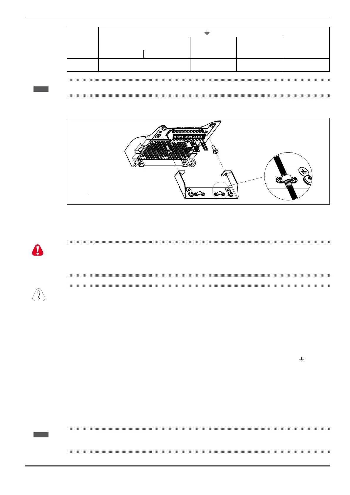
7.1.2 Connection of shielding (recommended)
A
B
C
Optional Power Shield kit:
- Cod. S726101 (sizes 1 and 2)
- Cod. S726501 (size 3)
Loosen the two screws (B), put the metal support (A) (optional, POWER SHIELD KIT) in place and screw down tightly.
Fasten the power cable shield to the omega sections (C) as illustrated in the
7.1.3 EMC guide line
In a domestic environment, this product may cause radio inference, in which case supplementary mitigation meas-
ures may be required.
Dans un environnement domestique, ce produit peut causer des interférences radio, auquel cas supplémentaire des
mesures d'atténuation peuvent être nécessaires.
The converters are protected in order to be used in industrial environments where, for immunity purposes, large
amounts of electromagnetic interference can occur. Proper installation practices will ensure safe and trouble-free
operation. If you encounter problems, follow the guidelines which follow.
- Check for all equipment in the cabinet are well grounded using short, thick grounding cable connected to a
common star point or busbar. Better solution is to use a conductive mounting plane and use that as EMC ground
reference plane.
- Flat conductors, for EMC grounding, are better than other type because they have lower impedance at higher
frequencies.
- Make sure that any control equipment (such as a PLC) connected to the inverter is connected to the same EMC
ground or star point as the inverter via a short thick link.
- Connect the return ground from the motors controlled by the drives directly to the ground connection (
) on the
associated inverter.
- Separate the control cables from the power cables as much as possible, using separate trunking, if necessary at
90º to each other.
- Whenever possible, use screened leads for the connections to the control circuitry
- Ensure that the contactors in the cubicle are suppressed, either with R-C suppressors for AC contactors or
the contactors are controlled from the inverter relay.
-
Use screened or armored cables for the motor connections and ground the screen at both ends using the cable clamps.
- Use Power shield kit to connect shield of motor cable to drive.
Note! For further information regarding electro-magnetic compatibility standards, according to Directive 2014/30/EU, conformity checks carried out on Gefran
appliances, connection of filters and mains inductors, shielding of cables, ground connections, etc., consult the “Electro-magnetic compatibility guide” on the
CD attached to this drive.
Warning!

 Loading...


