28 VDL200 • Quick installation guide - Specifications and connection
7.2 Regulation section
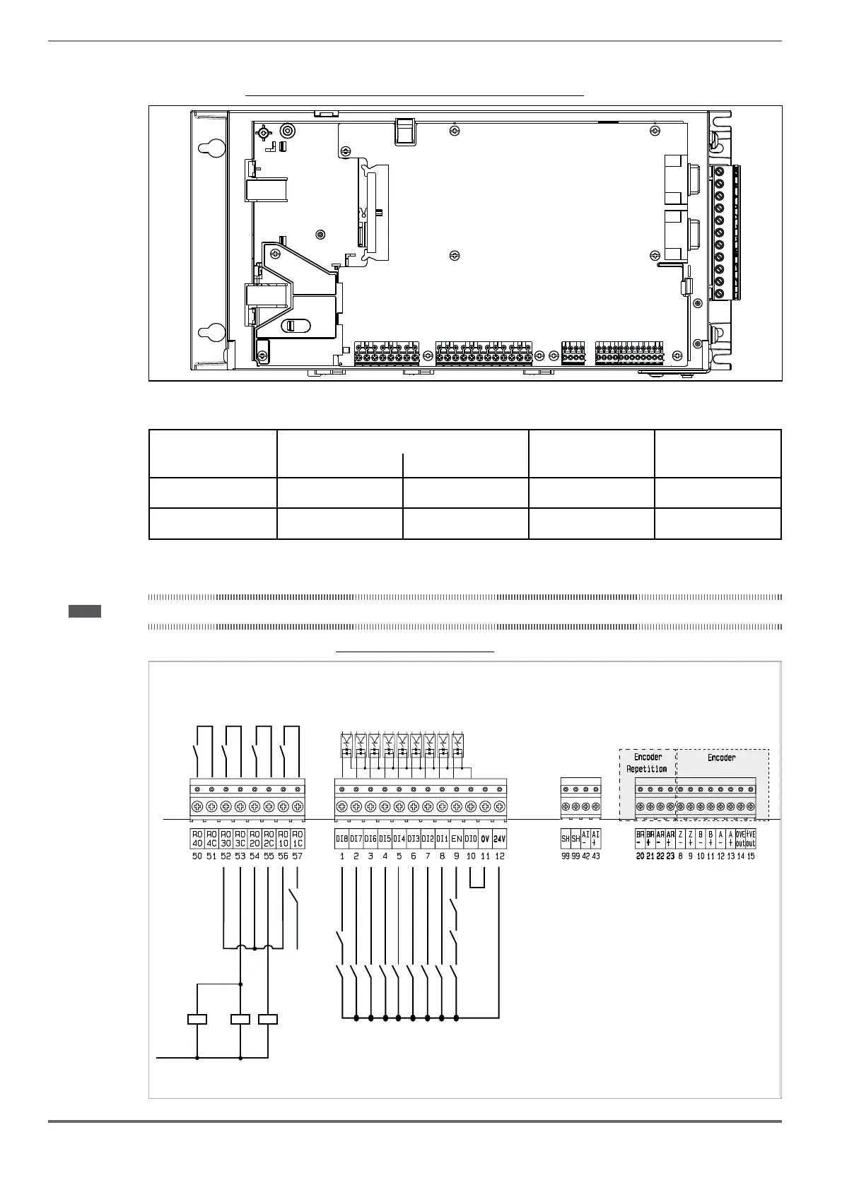
Figure 7.2.1VDL200 Asynchronous (R-VDL200 card)
PC/GF_eXpress
RS232
(D-SUB 9F)
Keypad
RS422
(D-SUB 9F / RJ45-8)
XS2
XS1
T3 T1 XER XE
R-VDL200
T2
7.2.1 Cable cross-sections
Terminals
Maximum cable cross-section Recommended stripping Tightening torque (min)
(mm
2
) (AWG) (mm) (Nm)
T3, T2, T1
0,2 ... 2.5 (1 cable)
0,2 ... 0.75 (2 cables)
26 ... 12
26 ... 19
5 0.4
XER, XE
0,2 ... 1.5 (1 cable)
0,2 ... 0.5 (2 cables)
26 ... 16
26 ... 19
5 0.25
7.2.2 Connection of I/O
Note!
For electrical properties of analog, digital and relay inputs/outputs see section "A.1 - I/O Specification".
Figure 7.2.3: terminal strip and connection
K2M
K3M
BrakeFbk
MltSpd S2
MltSpd S1
MltSpd S0
Emergency mode
StartRevCmd
StartFwdCmd
K3M K2M
Safety chain
Feedback contactor
L1
A1
A2
A1
A2
A1
A2
K2M
K3M
BR
Emergency
Failure
T3
T1
T2
XER
XE
Door
Run
Contactor
Brake
Contactor
Drive ON
Enable HW
Digital Input 8X
Digital Input 7X
Digital Input 6X
Digital Input 5X
Digital Input 4X
Digital Input 3X
Digital Input 2X
Digital Input 1X
+24V OUT
0V (24V) OUT
DI COM

 Loading...


