26 VDL200 • Quick installation guide - Specifications and connection
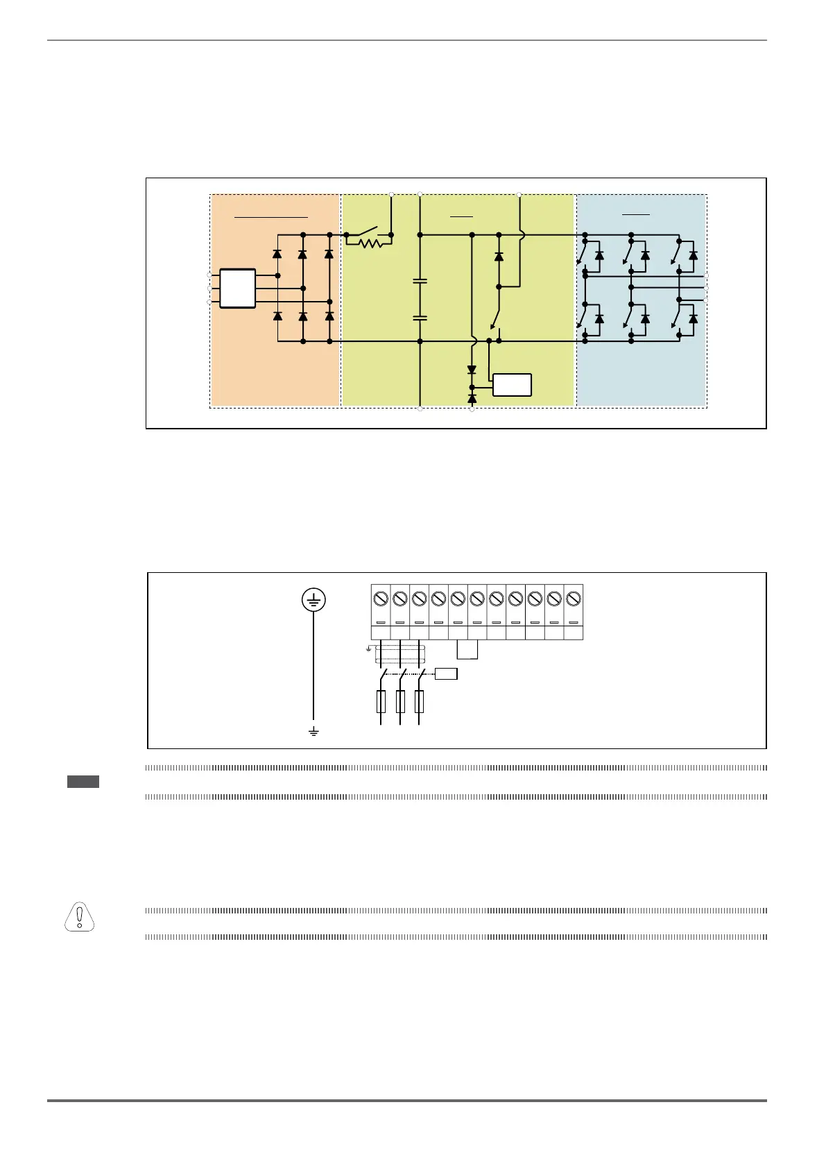
7.1.4 Block diagram of power section
VDL200-...-F), an AC/DC converter, a system for pre-loading DC
capacitors, a DC/AC converter, a power supply unit and an integrated braking unit.
To manage emergency situations (drive power failure) the unit also envisages connection of an emergency unit
between terminals EM and D.
connect the resistor between terminals
C and BR.
EMI
L1
L2
L3
Emifilter & converter
DC link
Inverter
Rprc
SMPS
C1 CBR
DEM
U
V
W
Filter (*)
(*) VDL200.-...-F-.. models
The VDL200-...-F-.. series of inverters are equipped with an internal EMI able to guarantee the performance levels
required by EN 12015 with max 10 m of shielded motor cable.
Compliance with these requirements means the drive can be incorporated into lift systems built to EN 12015.
7.1.6 Power line connection
L1 L2 L3 BR C1 CDUVWEM
K1M
L1 L2 L3
F1
(0 V/ 400 50/60 Hz)
AC3ph - 23 V/ 460-480 VAC AC,
Note! Recommended combination F1 fuses: see paragraph 5.1.1.
7.1.7 Connection of AC and DC chokes (optional)
The drive can use both a three-phase choke on the AC power line and, for 4 to 22 kW drives only, a DC choke between
terminals C1 and C. Refer to chapter 5.2 for the recommended connections.
If no DC choke is used on 4 to 22 kW drives, terminals C1 and C must be bridged.
If no DC choke is used, terminals C1 and C must be bridged (sizes 1, 2 and 3).
Attention

 Loading...


