PRINTED IN U.S.A. 63 913225/CP0807
b. Pivot the compressor assembly to obtain the
belt tension required.
c. Retighten screws.
COMPRESSOR TO ALTERNATOR BELT
- Check the belt tension between the compressor pul-
ley and of the alternator pulley.
- Under normal pressure exerted with the thumb of 10
lbf. (45N), the movement should be approximately
3/8” (10 mm).
- Adjustment if necessary:
a. Loosen mounting and adjuster screws two to
three turns.
b. Pivot the alternator assembly to obtain the belt
tension required.
c. Retighten screws.
- Replace the protective guard (2) (fig. C2/1).
NOTE: If the compressor belt is changed, check
the tension again after 20 hours of operation.
C3 - TRANSFER BOX OIL LEVEL
CHECK
Park the telescopic handler on level ground with the
engine stopped.
- Remove access panel (1) (fig. C3/1).
- Remove level plug (1) (fig. C3/2). The oil should be
flush with the edge of the filler port.
- If necessary, add oil (see chapter: 6 - MAINTE-
NANCE: D11 - TRANSFER BOX OIL) by the
same filler port.
- Replace and tighten the level plug (1) (fig. C3/2) 25
to 36 ft.-lb. (34 to 49 Nm) tightening torque.
C4 - PARKING BRAKE
CHECK - ADJUST
Place the telescopic handler on a slope less than 15 %
with the rated load in the transport position.
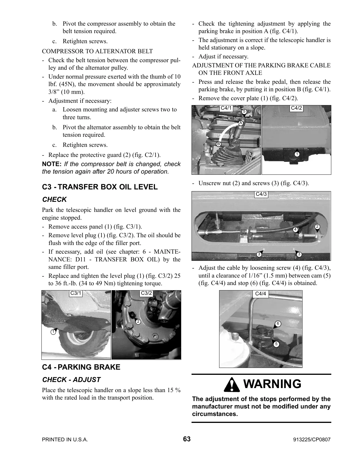
- Check the tightening adjustment by applying the
parking brake in position A (fig. C4/1).
- The adjustment is correct if the telescopic handler is
held stationary on a slope.
- Adjust if necessary.
ADJUSTMENT OF THE PARKING BRAKE CABLE
ON THE FRONT AXLE
- Press and release the brake pedal, then release the
parking brake, by putting it in position B (fig. C4/1).
- Remove the cover plate (1) (fig. C4/2).
- Unscrew nut (2) and screws (3) (fig. C4/3).
- Adjust the cable by loosening screw (4) (fig. C4/3),
until a clearance of 1/16” (1.5 mm) between cam (5)
(fig. C4/4) and stop (6) (fig. C4/4) is obtained.
WARNING
The adjustment of the stops performed by the
manufacturer must not be modified under any
circumstances.
C4/3
C4/4
2
3
3
4
5
6
C3/2
2
C3/1
1
C4/1
5
A
B
C4/2
1
Courtesy of CraneMarket.com
 Loading...