PRINTED IN U.S.A. 81 913225/CP0807
- Connect the quick-connectors as needed for the
attachment’s hydraulic movements.
IMPORTANT: Make sure that the quick-connec-
tors are clean, and protect the connections that
are not used with the caps provided.
MANUAL RELEASING AND DISCONNECTING
THE ATTACHMENT
- Proceed in the reverse order of paragraph MANU-
AL LOCKING AND CONNECTING THE
ATTACHMENT. Be sure to reinstall the locking pin
and the clip in the bracket (fig. A).
REMOVING AN ATTACHMENT
- Proceed in the reverse order of paragraph
INSTALLING AN ATTACHMENT. Be sure to
place the attachment flat on the ground and in a
closed position.
C - ATTACHMENT WITHOUT
HYDRAULICS, WITH HYDRAULIC
LOCKING DEVICE (Option)
INSTALLING AN ATTACHMENT
- Ensure that the attachment is in a position for lock-
ing it to the carriage. If it is not correctly oriented,
take the necessary precautions to safely position it.
- Check that the pins (1) on the locking cylinder are
retracted (fig. A).
- Park the telescopic handler with the boom lowered
in front of and in line with the attachment. Tilt the
carriage forward (fig. B).
- Bring the carriage under the mounting tube of the
attachment, slightly lift the boom, and tilt the car-
riage rearward to position the attachment (fig. C).
- Lift the attachment off the ground to ease locking.
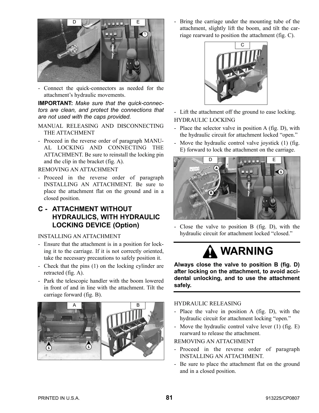
HYDRAULIC LOCKING
- Place the selector valve in position A (fig. D), with
the hydraulic circuit for attachment locked “open.”
- Move the hydraulic control valve joystick (1) (fig.
E) forward to lock the attachment on the carriage.
- Close the valve to position B (fig. D), with the
hydraulic circuit for attachment locked “closed.”
HYDRAULIC RELEASING
- Place the valve in position A (fig. D), with the
hydraulic circuit for attachment locking “open.”
- Move the hydraulic control valve lever (1) (fig. E)
rearward to release the attachment.
REMOVING AN ATTACHMENT
- Proceed in the reverse order of paragraph
INSTALLING AN ATTACHMENT.
- Be sure to place the attachment flat on the ground
and in a closed position.
E
1
D
WARNING
Always close the valve to position B (fig. D)
after locking on the attachment, to avoid acci-
dental unlocking, and to use the attachment
safely.
A B
1
1
C
D
B
A
E
1
Courtesy of CraneMarket.com
 Loading...