PRINTED IN U.S.A. 83 913225/CP0807
E - ATTACHMENT WITHOUT
HYDRAULICS, WITH HYDRAULIC
LOCKING DEVICE
With Tri-Function Joystick
INSTALLING AN ATTACHMENT
- Ensure that the attachment is in a position for lock-
ing it to the carriage. If it is not correctly oriented,
take the necessary precautions to safely position it.
- Check that the pins (1) on the locking cylinder are
retracted (fig. A).
- Park the telescopic handler with the boom lowered
in front of and in line with the attachment. Tilt the
carriage forward (fig. B).
- Bring the carriage under the locking tube of the
attachment, slightly lift the boom, and tilt the car-
riage rearward to position the attachment (fig. C).
- Lift the attachment off the ground to ease locking.
HYDRAULIC LOCKING
- Place the selector valve in position A (fig. D), with
the hydraulic circuit for attachment locking “open.”
- Press button (1) (fig. E) of the hydraulic control
valve joystick to lock the attachment on the carriage.
- Close the valve to position B (fig. D), with the
hydraulic circuit for attachment locking “closed.”
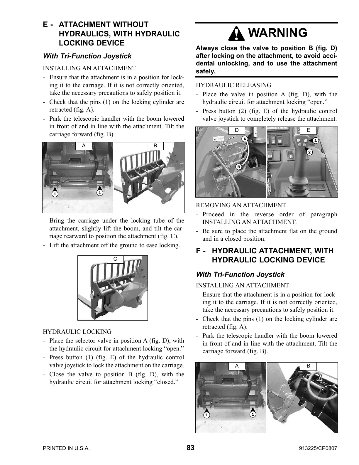
HYDRAULIC RELEASING
- Place the valve in position A (fig. D), with the
hydraulic circuit for attachment locking “open.”
- Press button (2) (fig. E) of the hydraulic control
valve joystick to completely release the attachment.
REMOVING AN ATTACHMENT
- Proceed in the reverse order of paragraph
INSTALLING AN ATTACHMENT.
- Be sure to place the attachment flat on the ground
and in a closed position.
F - HYDRAULIC ATTACHMENT, WITH
HYDRAULIC LOCKING DEVICE
With Tri-Function Joystick
INSTALLING AN ATTACHMENT
- Ensure that the attachment is in a position for lock-
ing it to the carriage. If it is not correctly oriented,
take the necessary precautions to safely position it.
- Check that the pins (1) on the locking cylinder are
retracted (fig. A).
- Park the telescopic handler with the boom lowered
in front of and in line with the attachment. Tilt the
carriage forward (fig. B).
WARNING
Always close the valve to position B (fig. D)
after locking on the attachment, to avoid acci-
dental unlocking, and to use the attachment
safely.
A B
C
1
1
D E
1
2
A
1
1
B
B
A
Courtesy of CraneMarket.com
 Loading...