Printed in U.S.A. 103 913364/BP0314
RT250 - HYDRAULIC SYSTEM
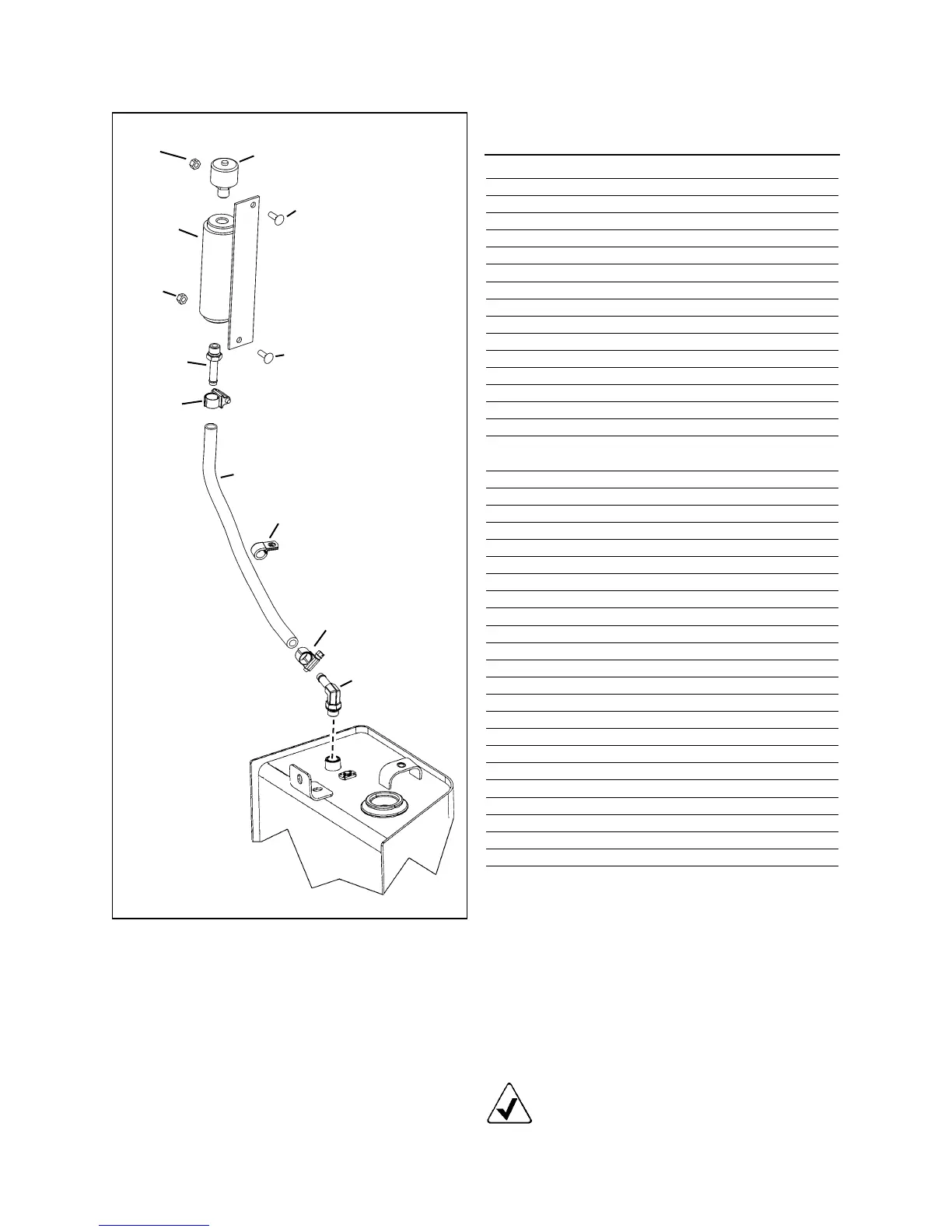
HYDRAULIC TANK
(Early-Style Tank - identified by vent system and fill plug #6)
01 50302527 WELDMENT, HYDRAULIC TANK 1
02 139438 CS FL LOCK 3/8” x 5/8” 3
03 194180 90 HB06-MAORB06 1
04 131913 BUMPER 1
05 653034 HLN 5/16” C2ZY 1
06 271689 PLUG, -24 (hydraulic oil fill) 1
07 274125 O-RING (included with item 6) 1
08 131577 PLUG MORB10 1
09 055898 O-RING (included with item 8) 1
10 131522 PLUG MORB12 1
11 048953 O-RING (included with item 10) 1
12 055064 45 MJ12-MAORB12 1
13 50301262 HOSE, MP12 x 75 IN. 1
14 230-32412 ADAP., MAORB20-BARB 1
15 077970 O-RING (included with item 14) 1
16 193743 CLAMP, T-BOLT 1.75 IN. 1
17 50301897 HOSE, LP 20 x 88.0 IN. (suction) 1
50300818 GUARD, POLY HOSE (not shown) 1
18 137599 HOSE, MP12 x 26.0 IN. (Std. Hyd.) 1
19 055064 45 MJ12-MAORB12 1
20 273867 HOSE, MP 6 x 74.0 IN. 1
21 50301382 HOSE, MP4 x 67.0 IN. 1
22 079026 45 MJ06-MAORB06 2
23 273907 HOSE, MP8 x 49.0 IN. 1
24 076880 45 MJ08-MAORB08 1
25 134756 SIGHT PORT (oil level) 1
26 274125 O-RING (included with item 25) 1
27 122778 PLUG, MORB06 (stnd. hydraulics) 1
28 068938 ADAP., MJ06-MAORB06 1
29 274114 HOSE, MP 6 x 110.0 IN. 1
30 071700 LN 1/4 CBZY 2
31 50302525 BREATHER 1
32 651086 CB 1/4" x 1" C5ZY 1
33 650758 CB 1/4" x 3/4" C5ZY 1
34 50302530 BREATHER STANDPIPE 1
35 50301160 ST HB06-MORB06 1
36 087852 HOSE CLAMP #06 2
37 50302537 HOSE, FUEL 3/8" x 16" 1
38 L71042 CLAMP, VINYL 0.50" x 0.28" 1
42 50302969 HOSE, MP 16 x 56 " * 1
47 088117 90 MJ16-FJS16 * 1
48 054818 ST MJ16-MORB12 * 1
* Used when machine is equipped with high-flow
hydraulics option on early-style machines.
Item
No. Part No. Description Qty.
31
30
34
32
35
36
37
38
36
3
30
33
Top of Hydraulic Tank
HOSE CONNECTION:
#13 connects to T1 on Pilot Pressure Manifold
#17 connects to hydraulic pump
#18 connects to hydraulic cooler (upper port) — connects to
steel tube on early machines or directly to the cooler
on later machines.
#20 connects to auxiliary hydraulics (loader arm left side)
#21 connects to hydraulic main valve (bottom TEE)
#23 connects to "TEE" on right side drive motor
#29 connects to High-Flow hydraulics (loader arm right side)
#42 connects to hydraulic cooler (upper port) **
NOTE: Be aware when ordering items 18,19, 42,
47, and 48 that early- and late-style machines used
different hoses and fittings. For additional informa-
tion, refer to the hydraulic cooler shown on pages
72 and 74.
Hydraulic Tank
Vent System