5 - 8 DPL-25S • DPL-30S • DPL-35S Super Series Part No. 40462
September 2016
Section 5 - Troubleshooting Flow Charts
CHART 3
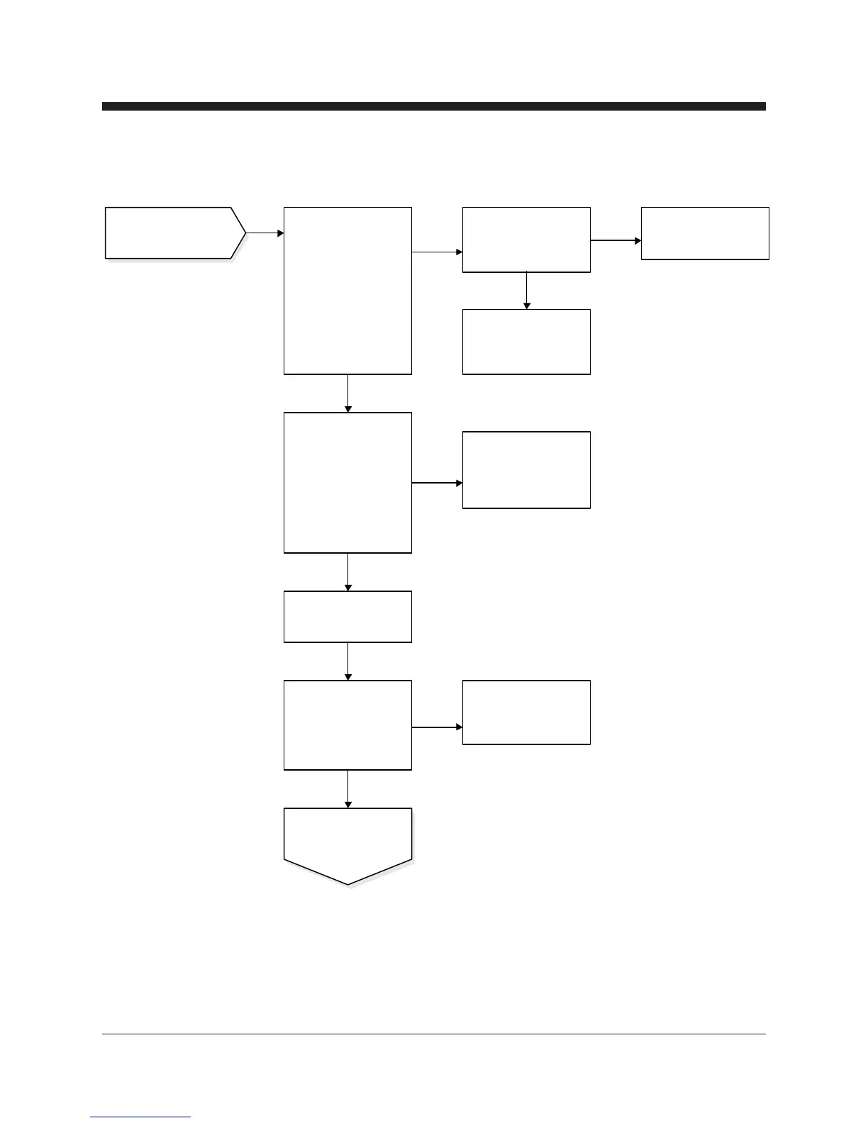
Inspect the outrigger
interlock contacts and the
base interlock contacts
for damage.
Replace P.C. board OR
consult Genie Industries
Service Department.
0V DC
12 V DC
0V DC
Continued from the
previous page.
Repair or replace
damaged interlock
contacts.
If LED 2 is not on, check
for power at the wire nut
where the red wire from
outrigger switch 2
connects to the orange
wire. If LED 3 is not on,
check for power at the
wire nut where the red
wire from outrigger switch
3 connects to the blue
wire.
good
Repair open circuit in the
black wire or the red wire
from base interlock
contacts.
bad
12V DC
Check for power at the
black wires that are
connected together with a
wire nut located in the
steer handle-end junction
box.
0V DC
Replace 18/7 cable from
the ladder-end junction
box because of open
circuit in orange wire or
blue wire .
If LED 2 is not on, check
for power at terminal 5
(orange wire). If LED 3
is not on, check for
power at terminal 6 (blue
wire). These terminals
are on the 13 pole
terminal strip (J1) in the
ground control box.
Continued on the next
page.
Replace 18/7 cable from
ladder-end junction box
because of open circuit in
black wire.
If LED 1 or 4 are not
on, continue from here
12 V DC
 Loading...