GCL-GCX
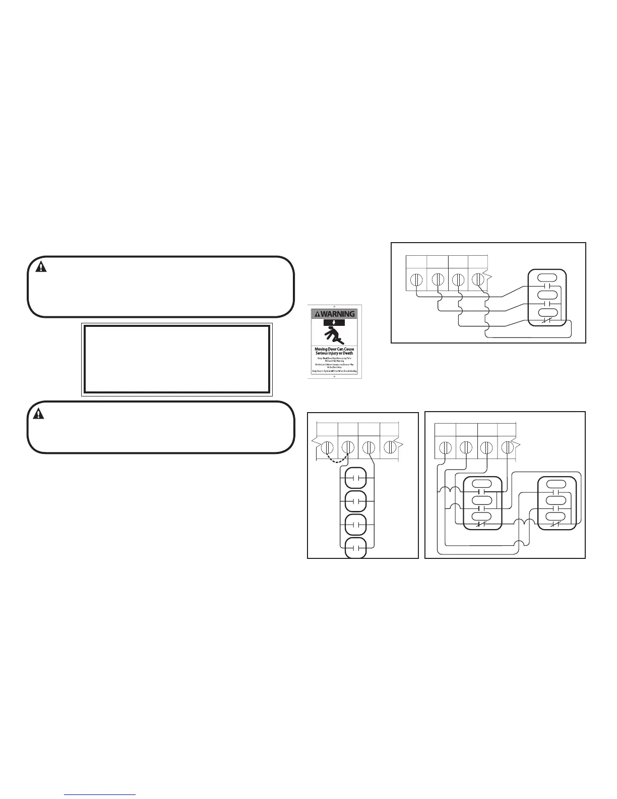
1) For one 3 - button installation, make connections as
shown in Fig. 3.
2) For single button accessory controls, make connections as
shown in Fig. 4.
3) For a multiple 3 - button installations, make connections as
shown in Fig. 5.
NOTE: If an External STOP button is NOT being installed, a jumper wire
must be installed between the “STOP” AND “GND” terminals as shown.
NOTE: Long Distance Relay Kit wiring is not required for long
distance control runs and should not be used
Wall Control
WARNING:
• Wall Control(s) must be located so that the door is within sight of
the user.
• Attach the Warning placard adjacent to the Wall Control. Fig. 3A.
• Attach the Caution Label adjacent to the Wall Control. Fig. 3B.
WARNING:
If momentary contact control is to be used, an external monitored reversing
device such as a photocell system or sensing edge switch must be used. See
pages 5.6-5.7 for installation of entrapment protection devices.
NOTE:
JUMPER BETWEEN
STOP AND GND
TERMINALS MUST
BE REMOVED
3-BUTTON
STATION
CONTROL SIGNAL TERMINAL STRIP
OPEN CLOSE STOP GND
3-BUTTON
STATION
OPEN
CLOSE
STOP
OPEN
CLOSE
STOP
Figure 4
1-BTN
STATION
KEY
SWITCH
STATION
CARD
READER
OPEN/CLOSE
PULL SWITCH
CONTROL SIGNAL TERMINAL STRIP
ODC
STB
GNDSTOP 1-BTN
Figure 5
OPEN
CLOSE
STOP
3-BUTTON
STATION
CONTROL SIGNAL TERMINAL STRIP
NOTE:
JUMPER BETWEEN
STOP AND GND
TERMINALS MUST
BE REMOVED
OPEN CLOSE STOP GND
Figure 3
11 35 0 1
Entrapment
Warning
Placard
Figure 3A
Figure 3B
CAUTION
To prevent the motor protector from tripping,
do not exceed 4 door operations per hour.
For light-duty use ONLY
Not for residential use.
P/N 111980.0001
5.4
www.geniecompany.com 08-12
Counter Door Operator
 Loading...