5.5
Photocell Wiring
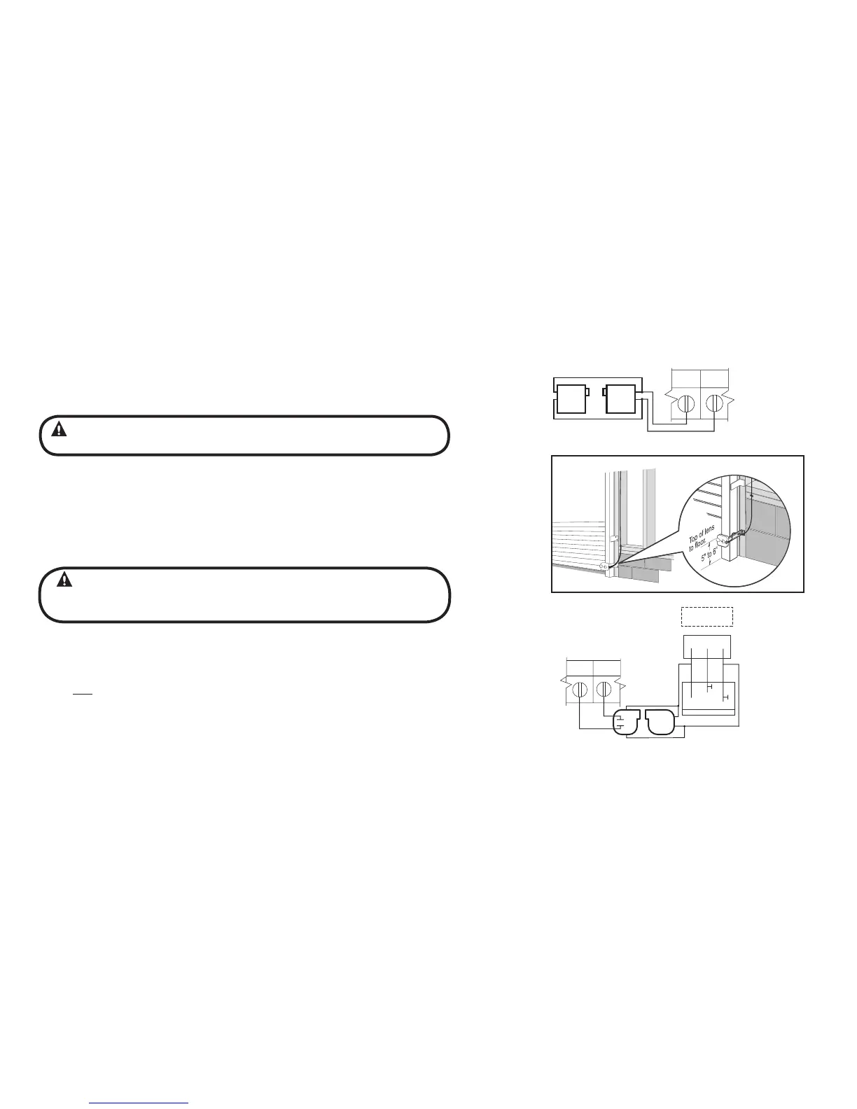
1) Monitored SERIES II (STB) photocells (P/N 38176R.S or OPAKPE.S) can be installed as shown in
Fig. 6. Wiring to these photocells can be connected to either terminal (they are
not polarity sensitive). ( Troubleshooting in Section 8).
NOTE: Installer must enable ODC STB in calibration mode. See page 6.7.
2) To Mount Photocells: (Kit includes detailed Instructions).
• Determine location for mounting. They do not need to be directly adjacent to
the door but must be somewhere along the wall where there will be an
unobstructed line between them. Fig 7.
• Screws provided for mounting on soft material (wood, drywall, etc.)
• They must extend out away from the wall sufficiently that no door hardware
breaks the plane of the photo-beam.
1) Nominal 24 Volt DC Commercial photocells with normally open contacts can be
connected as shown in Fig. 8.
NOTE: Blue wire supplies 20 – 40VDC. Photocells used must be compatible with this
voltage range.
NOTE: If no voltage is present at Blue wire, check fuse F-1
on Control board.
Series II Safe-T-Beam® Monitored Photocells
Commercial Non-Monitored Photocells
WARNING:
Photocell systems provide entrapment protection when
mounted near the doorway in such a way that the lower portion of an individual’s
leg will break the photocell beam during normal walking conditions.
WARNING:
Actuating operator using constant contact on the CLOSE button will
override external reversing devices, including photocells.
SERIES II (STB)
RESIDENTIAL SAFE-T-BEAMS
®
CONTROL SIGNAL
TERMINAL STRIP
ODC
STB
ODC
STB
Figure 6
CONNECT WIRES TO EITHER TERMINAL.
(NOT POLARITY SENSITIVE
)
Figure
7
N-O
REVERSE
N-O
REVERSE
+
-
+
-
THRU-BEAM
PHOTOCELLS
CONTROL SIGNAL
TERMINAL STRIP
RECEIVER
TRANSMITTER
EXT RADIO CONNECTOR
PWR
20 40 VDC @ 315mA
MAX CURRENT
RELAY
GND
NOM
+ 24VDC
RADIO
Blue
Orange
Ye low
Figure 8
www.geniecompany.com 08-12
Counter Door Operator
GCL-GCX
 Loading...