Zoom90 | 30Operation
To remove the USB stick, open the lid of the compartment and slide the USB stick out of the port.
4.9 Working with Bluetooth
Description Zoom90 instruments can communicate with external devices by a Bluetooth connection. The instrument
Bluetooth is a slave only. The Bluetooth of the external device will be the master, and therefore will control
the connection and any data transfer.
Establishing a connec-
tion step-by-step
1) On the instrument ensure that the communication parameters are set to Internal Bluetooth or Blue-
tooth Handle. Refer to "5.3 Communication Settings".
2) Activate Bluetooth on the external device. The steps required depend on the Bluetooth driver and other
device specific configurations. Refer to the device user manual for information on how to configure and
search for a Bluetooth connection.
The instrument will appear on the external device.
3 Some devices ask for the identification number of the Bluetooth. The default number for a Zoom90
Bluetooth is 0000. This can be changed by:
• Select Settings from the MAIN MENU.
• Select Comm. from the SETTINGS menu.
• Press CONF from the COMMUNICATION SETTINGS screen.
• Choose Pin from the Internal Bluetooth screen. Enter a new Bluetooth code.
• Press OK to confirm the new Bluetooth code. Before the new Pin will be active, a reboot of the
system would be required.
4 When the external Bluetooth device has located the instrument for the first time, a message will display
on the instrument stating the name of the external device and requesting confirmation that connection
to this device should be allowed.
• Press YES to allow, or
• Press NO to disallow this connection
5 The instrument Bluetooth sends out the instrument name and serial number to the external Bluetooth
device.
6 All further steps must be made in accordance to the user manual of the external device.
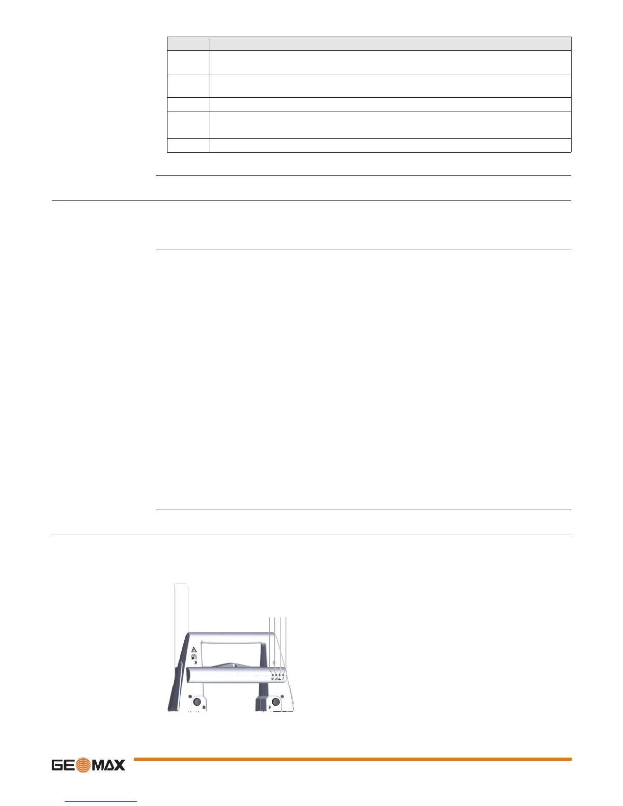
4.10 LED Indicators
LED Indicators on Radi-
oHandle
Description
The RadioHandle has Light Emitting Diode indicators. They indicate the basic RadioHandle status.
Diagram of the LED Indicators
Step Description
The USB stick is inserted into the USB host port inside the Communication side cover of the
instrument.
1. Turn the knob on the Communication side cover to the vertical position to unlock the commu-
nication compartment.
2. Open the lid of the communication compartment to access the communication ports.
3. Slide the USB stick firmly into the USB host port until it clicks into position.
Do not force the USB stick into the port.
4. Close the lid and turn the knob to the horizontal position to lock the compartment.
a) Power LED
b) Link LED
c) Data Transfer LED
d) Mode LED
009860_001
abcd
 Loading...