24 LRR 1-52, LRR 1-53, URB 55 - USA - Installation & Operating Manual - 850703-00
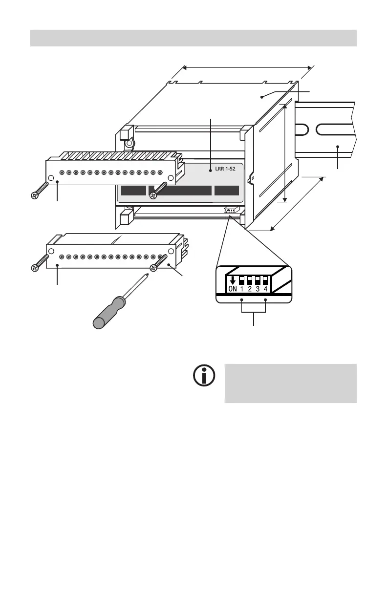
A Upper terminal strip
B Lower terminal strip
C Fastening screws (M3)
D 4-pole code switch for configuring the
conductivity controller
E Front membrane with status LED,
see page 24
F Terminal box
G Support rail TH 35
Functional elements and dimensions of the LRR 1-52, LRR 1-53
The code switch can be accessed by
disconnecting and removing the lower
terminal strip.
Equipment settings,
see page 24.
Fig. 8
123456789101112131415
1
2
MAX
1
2716 17 18 19 20 21 22 23 24 25 26 28 29 30
12345678910 11 12 13 14 15
100
73
118
1
2
MAX
1
2716 17 18 19 20 21 22 23 24 25 26 28 29 30
A
B
C
F
G
D
E
3.94 in (100 mm)
2.87 in (73 mm)
4.65 in (118 mm)

 Loading...


