62 LRR 1-52, LRR 1-53, URB 55 - USA - Installation & Operating Manual - 850703-00
Configuring the conductivity controller
Setting the control parameters
Parameter Control deviation Control valve
Proportional
band
Pb
> larger Large remaining deviation Reacts slowly
< smaller Small remaining deviation
Reacts quickly and may open/close
continually
Example:
Measuring range 0 to 3000ppm (0 to 6000µS/cm)
Set point SP = 1500ppm (3000µS/cm)
Proportional band Pb = +/- 20% of set point = +/- 300ppm (600µS/cm)
With the measuring range and set point mentioned above, the proportional band
is then +/- 300ppm (600µS/cm) or in the range from 1200ppm (2400µS/cm)
to 1800ppm (3600µS/cm).
Reset time
Ti
> larger Slow correction of deviations Reacts quickly
< smaller
Fast correction of deviations, the control
loop may tend to overshoot
Reacts slowly
Dead
band
> larger
Correction of deviations starts with a
delay
In this range, the manipulated variable
does not change.
Only reacts when the control
deviation is larger than the “dead
band”.
< smaller Correction of deviations starts rapidly
Valve runtime
Tt
Establish the real valve runtime, e.g.,
from “Closed” to “Open” (0 - 100%).
Operating
position
Defined opening of the continuous
blowdown valve. Closes on standby.
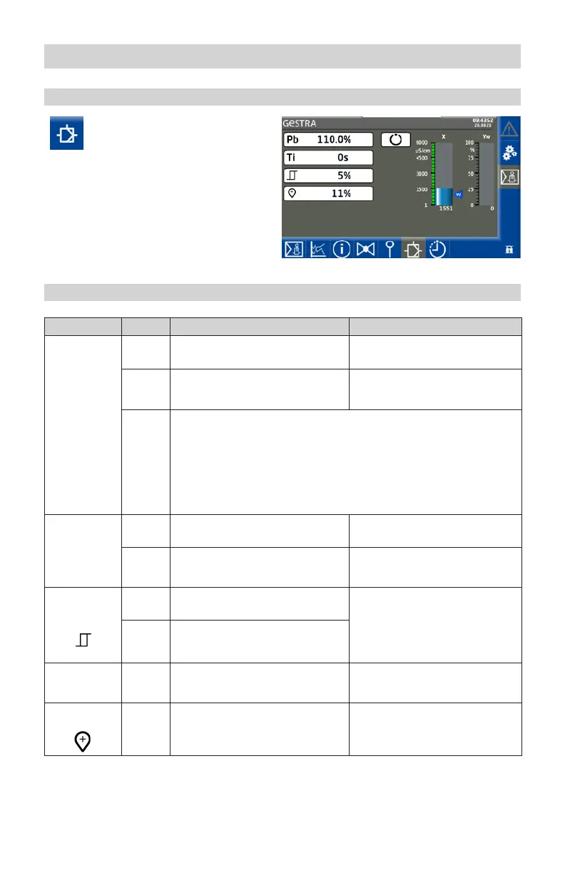
Fig. 23
Open the control parameter
screen.
Guide to setting control parameters

 Loading...


