28 LRR 1-52, LRR 1-53, URB 55 - USA - Installation & Operating Manual - 850703-00
A
C
D
B
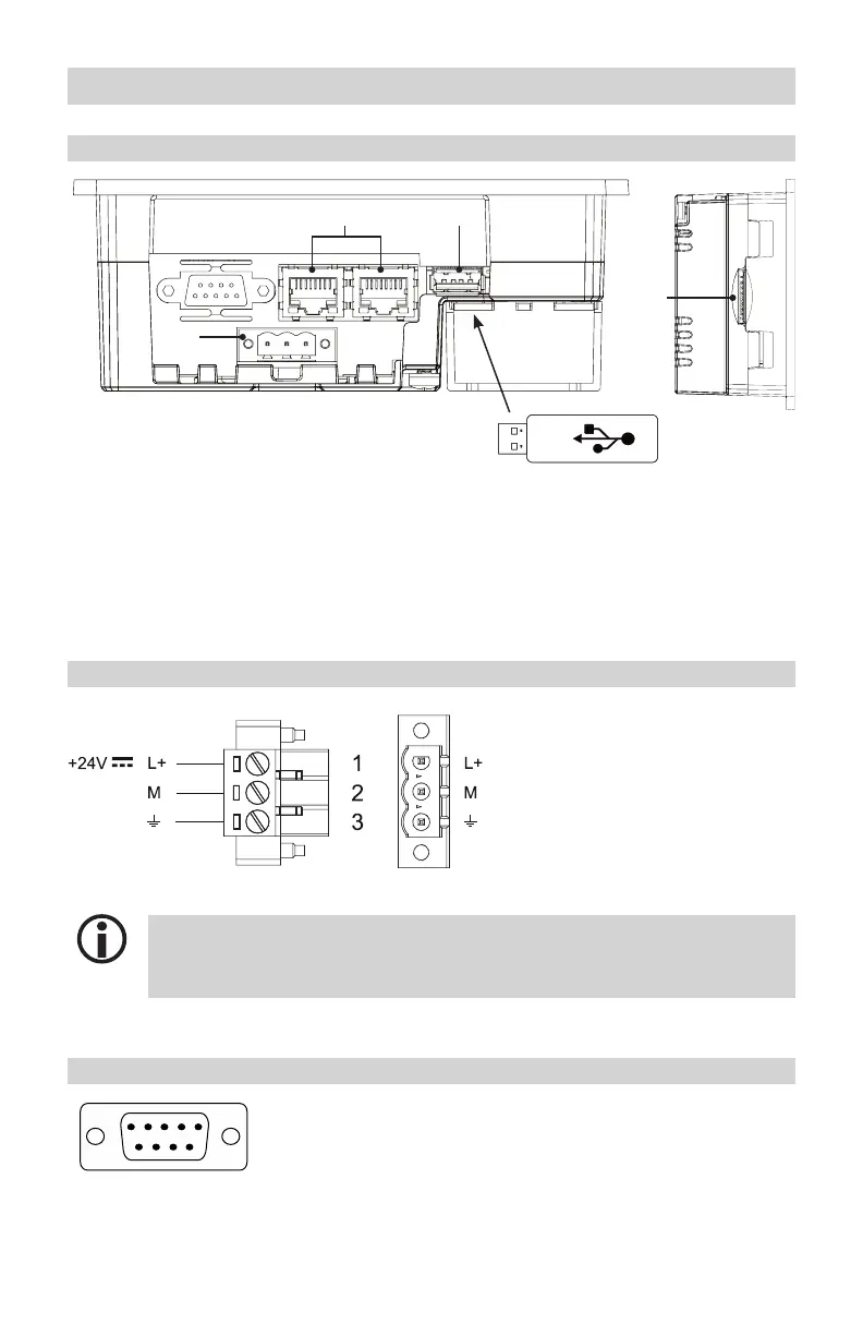
Connecting the URB 55
Ports and sockets on the back of the unit
Fig. 13
A 1 x 3-pole connector for 24V DC supply voltage
B 2 x Ethernet ports 10/100Mbit switched (Modbus TCP/IP)
C 1 x
USB host port (versions 2.0 and 1.1) for USB sticks with FAT32/FAT or exFAT file format
D 1 x slot for SD card with FAT32 file format (for service purposes) *
* SDHC memory cards are not supported.
(L-) (L-)
Connection for 24V DC supply voltage - pin assignment
Connector SocketFig. 14
Use a SELV (Safety Extra Low Voltage) power supply unit for connecting the supply vol-
tage. To connect the supply voltage to the supplied 3-pole connector, use a cable with a
max. wire size of AWG14 (2.5 mm
2
).
Pin assignment of data line between URB 55 and LRR 1-52, LRR 1-53
9
1
Pin 2 = Data_L >> LRR 1-52, LRR 1-53 = terminal 12
Pin 7 = Data_H >> LRR 1-52, LRR 1-53 = terminal 11
Fig. 15

 Loading...


