56 LRR 1-52, LRR 1-53, URB 55 - USA - Installation & Operating Manual - 850703-00
Configuring the conductivity controller
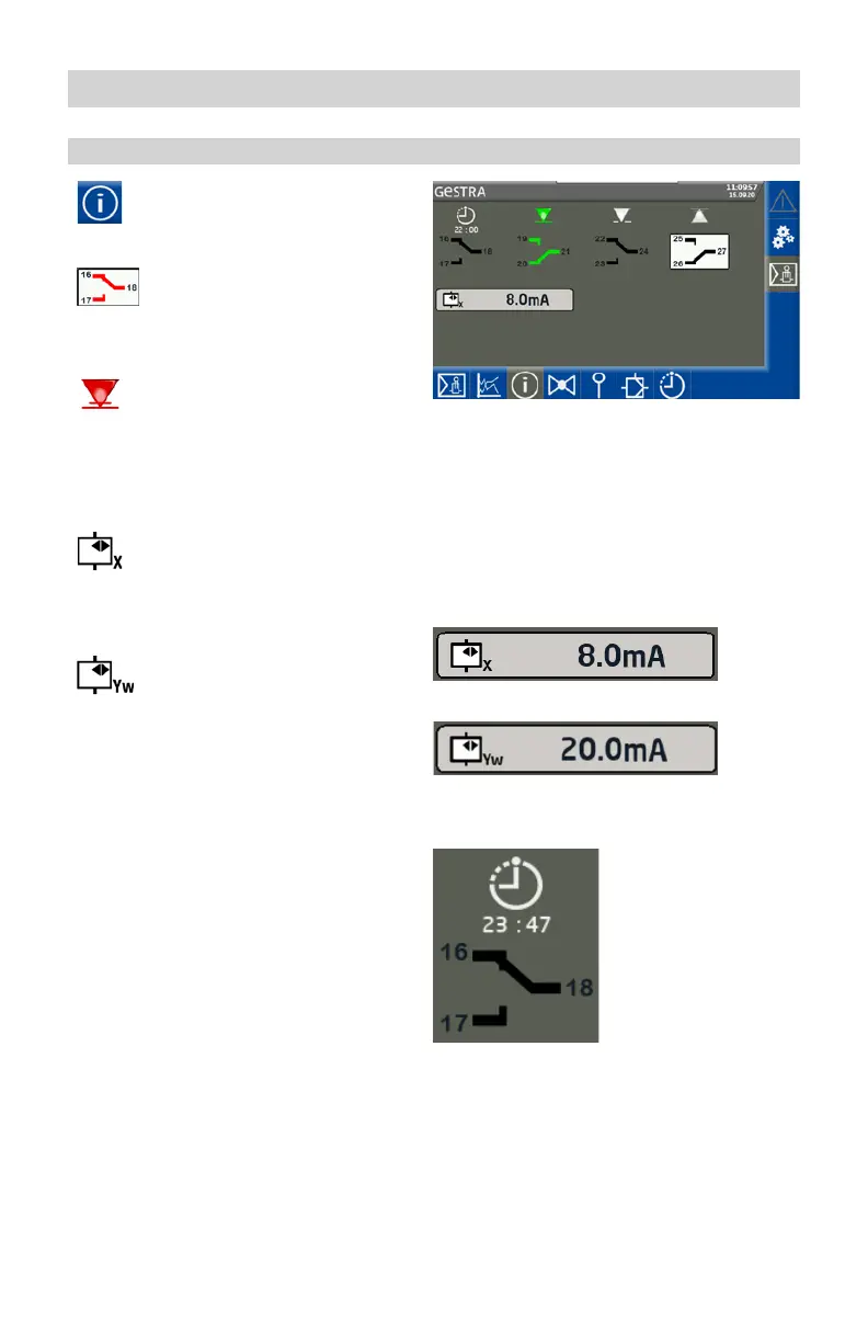
Test - Testing the relays of the connected conductivity controller
Open the Info/Test menu to test the
alarm and switching contacts of
the connected controller.
Press the button to initiate the relay
test.
This causes actual tripping of relay
contacts in the controller.
The relevant icons are shown in the
top part of the screen, depending
on the configuration (example).
The relay in the controller remains
active as long as you are pressing
the button.
Actual value output 4 - 20mA,
display of current actual value (X) *
or
Manipulated variable output 4 -
20mA, display of current manipu-
lated variable (Yw) *
* Controller software version
311178.13 or later
View if configured as an intermittent
blowdown controller
If the MIN relay is configured as an
intermittent blowdown controller, the icons on
the display change accordingly.

 Loading...


