58 LRR 1-52, LRR 1-53, URB 55 - USA - Installation & Operating Manual - 850703-00
Configuring the conductivity controller
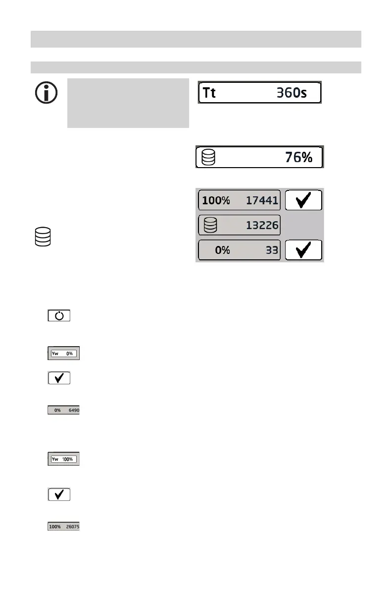
Calibrating the feedback potentiometer for a display of the continuous blowdown valve position
Even with a feedback potentio-
meter connected to the controller,
the valve runtime still needs to be
established and entered precisely.
1. Tap the parameter display.
The current raw values then appear.
100% (OPEN) / 0% (CLOSED)
Calibrated valve positions.
The calibrated raw data is shown
in both fields.
Raw data
Indicates the current digital
valve position.
Performing calibration
2.
Press the Automatic
button and switch to
manual mode.
3.
Enter “0%” as the
manipulated variable (Yw).
4.
When the valve is in the
(CLOSED) end position,
confirm this position
.
5.
The raw data from the central
field is automatically
entered in the 0% (CLOSED)
field.
6.
Next, enter “100%”
as the manipulated variable
(Yw).
7.
When the valve is in the
(OPEN) end position,
confirm this position
.
8.
The raw data from the central
field is automatically
entered in the 100% (OPEN)
field.

 Loading...


