53LRR 1-52, LRR 1-53, URB 55 - USA - Installation & Operating Manual - 850703-00
Configuring the conductivity controller
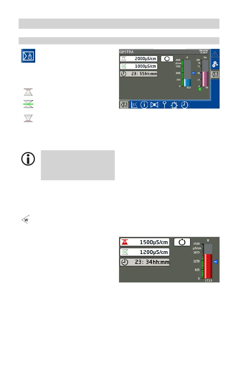
Setting the MIN/MAX switchpoints and set point
Open the parameter screen.
LRR 1-52 conductivity controller (example)
Description of parameters:
MAX alarm switchpoint
Set point
MIN alarm switchpoint
For each switchpoint, press the relevant button
and enter the required value using the virtual
keypad.
The icons in the buttons change
color to indicate switchpoints/
alarm points that are too high or
too low.
Description of bar charts:
X Actual value
W Set point
The set point is shown with a small
arrow in the actual value bar chart.
Yw Manipulated variable
Change of color on alarm
The bar chart column turns red in the event
of an alarm.

 Loading...


