46 LRR 1-52, LRR 1-53, URB 55 - USA - Installation & Operating Manual - 850703-00
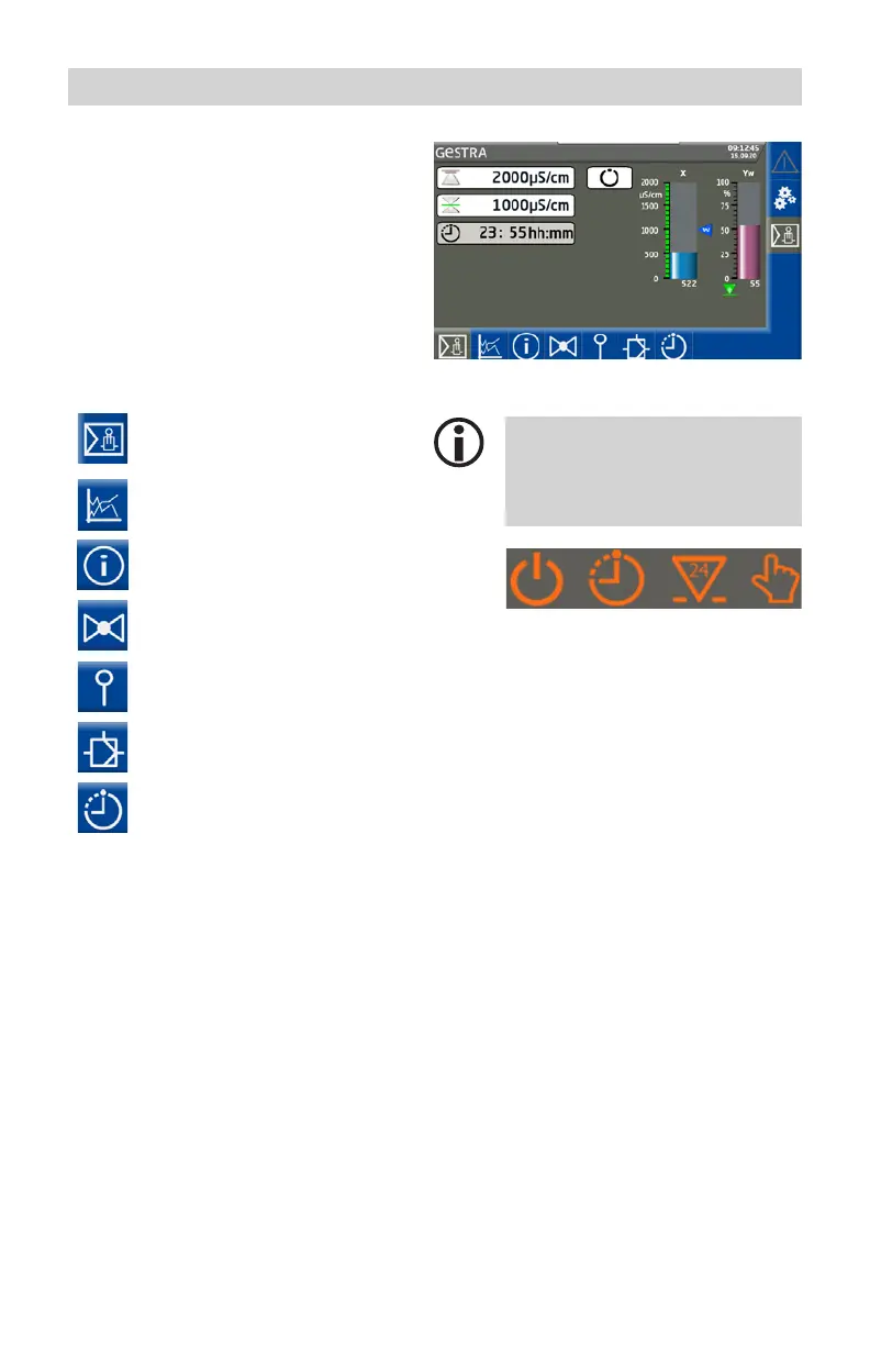
Home screen of LRR 1-52, LRR 1-53 conductivity controllers
The home screen provides an overview of the
controller status and parameters. Bar charts
display current readings and change color
depending on their status. This enables you to
rapidly assess the plant status.
Icons on the bar charts indicate the status of
the connected electrode.
Opening the parameter screens:
Use the following buttons to open the control-
ler parameter screens:
Switchpoints,
see page 46
Trend,
see page 46
Test / Controller information,
see page 46
Valve control,
see page 46
Calibration of conductivity elec-
trode, see page 46
Set controller parameters,
see page 46
Set automatic intermittent blow-
down, see page 46
Further icons appear below the bar
charts, depending on the configu-
ration. These are explained in the
sections below.
A Standby (mode)
B Intermittent blowdown (active)
C 24h flushing
D Manual (mode)
A B C D

 Loading...


