27
MDE-5222F
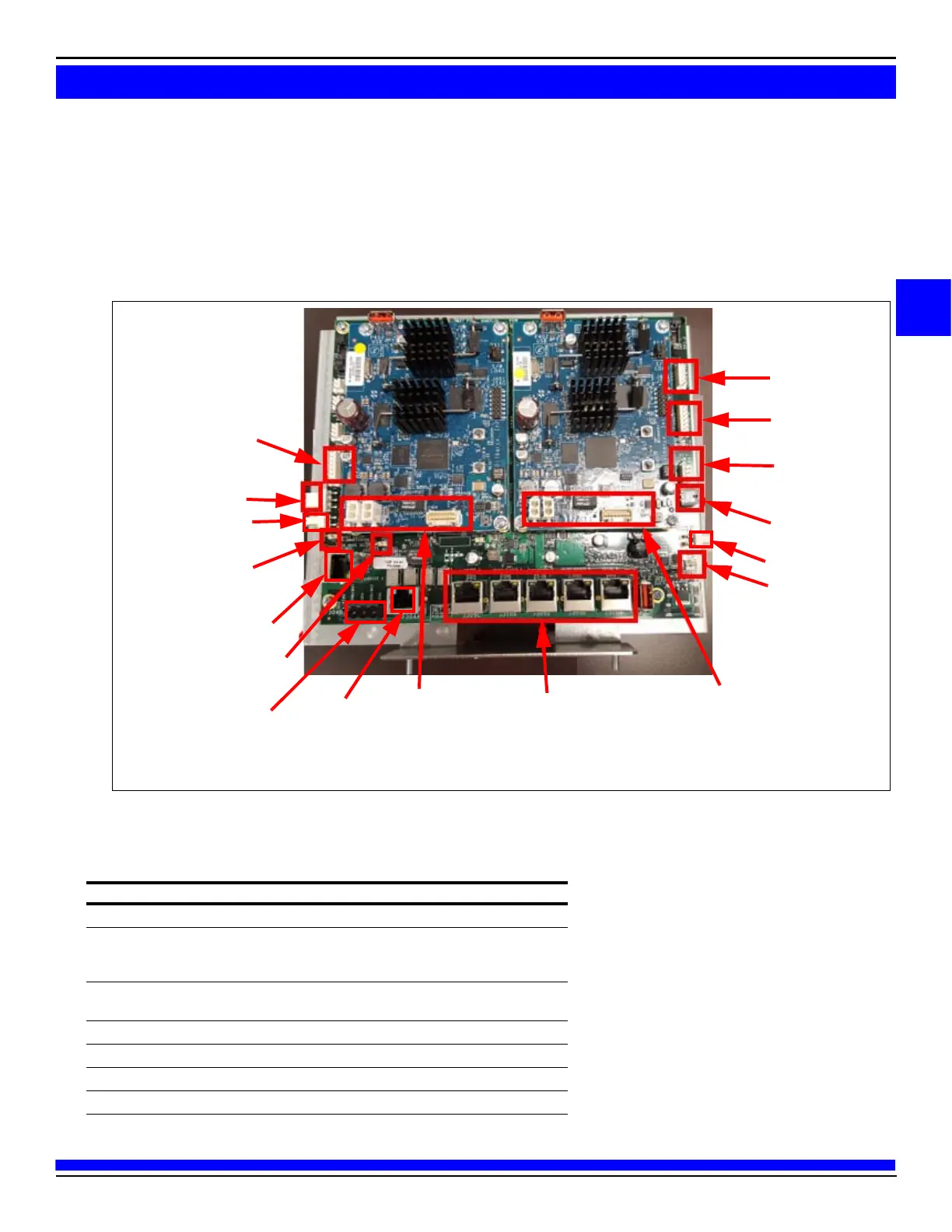
5 Replace the 24 VDC M07973A006 Power Cable in place of M07973A004 and make the following
connections:
• Connect P305 to J305.
• Connect J401 to P301 on the DCM2.2 assembly.
• Connect power to each CRIND (J301A to P301A/B and J301B to P301A/B).
Figure 11: Connecting Cables to DCM2.2 Assembly
ZMODEM* Serial
Connection to Pump
P302B Serial
Connection to
Side B Door
P300 Pump and
CRIND Two-Wire
to High Speed
P306 Two-Wire
Connection to Pump
P333 Dedicated
High Speed
Audio and video Cables
from Side B Door to
GSOM
Ethernet Connection
Audio and video
Cables from
Side A Door to GSOM
High Speed (HomePlug)
Jumper
P302A Serial Connection
to Side A Door
P301 Power Cable
Jumper Configured
for Generic and MOC
mode Selection
P306B Power Cable
P304A
Backroom
Ethernet
Connection
Backroom
Connection
Laptop Service Port
P306A Power Cable
Note: * ZMODEM is for Encore 500 only.
DCM2.2 Connectors
The following table lists the port numbers and functions of DCM2.2 connectors:
DCM2 Connector Port Number Function
3-pin MTA .156” P301 24 VDC power input
2-pin MTA .156” P306A 24 VDC power output (fused). This is primarily
used to pow
er the DCM in Applause Media
System.
5-pin MTA .100” P300 Two-wire from D-Box [CRIND and Pump
(Gener
ic only)].
2-pin MTA .100” P303 Two-wire connection to PCN
8-pin MTA .100” P302A RS-232 pump and CRIND to PIP3 A
4-pin P333 Dedicated Home Plug
8-pin MTA .100” P302B RS-232 pump and CRIND to PIP3 B
 Loading...