30
– Semi-rigid metallic tubing and metallic fittings.
Aluminum alloy tubing must not be used in exterior
locations. In order to seal the grommet cabinet
penetration, rigid pipe must be used to reach the
outside of the cabinet. A semi-rigid connector to the
gas piping may be used from there.
• Use listed gas appliance connectors in accordance with their
instructions. Connectors must be fully in the same room as
the furnace.
• Protect connectors and semirigid tubing against physical
and thermal damage when installed. Ensure aluminum-alloy
tubing and connectors are coated to protect against external
corrosion when in contact with masonry, plaster, or insulation,
or subjected to repeated wetting by liquids such as water
(except rain water), detergents, or sewage.
The gas piping may enter the left or right side of the furnace
cabinet. The installer must supply rigid pipe long enough to reach
the outside of the cabinet to seal the grommet cabinet penetra-
tion. A semi-rigid connector to the gas piping can be used outside
the cabinet per local codes. 1/2” NPT pipe and fittings are re-
quired. For models with an “L” shaped manifold, a 4 1/2”
long nipple is required. For models with a hook shaped mani-
fold, a 2” long nipple is required.
A semi-rigid connector to the gas piping can be used outside
the cabinet per local codes. From the elbow, the length of pipe
and the fittings required will vary by the side chosen, location
of union and cabinet width. The union may be placed inside or
outside of the cabinet.
Alternate
Gas Line
Location
Gas Valve
Burners
Manual Shut Off Valve
(upstream from
ground joint
pipe union)
Drip Leg
Grommet
in Standard
Gas Line
Hole
*Ground
Joint
Pipe
Union
*Ground
Joint
Pipe
Union
*NOTE: Union may be inside furnace cabinet where allowed by local codes.
Manifold
UPFLOW
Figure 36
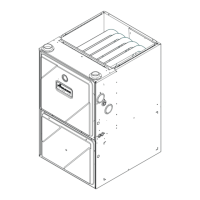
Alternate
Gas Line
Location
Plug in
Alternate
Gas Line
Hole
Gas Valve
Burners
Manual Shut Off Valve
(upstream from ground joint pipe union)
Drip Leg
Grommet
in Standard
Gas Line
Hole
*Ground
Joint
Pipe Union
*Ground
Joint
Pipe Union
*NOTE: Union may be inside furnace cabinet where allowed by local codes.
COUNTERFLOW
Figure 37
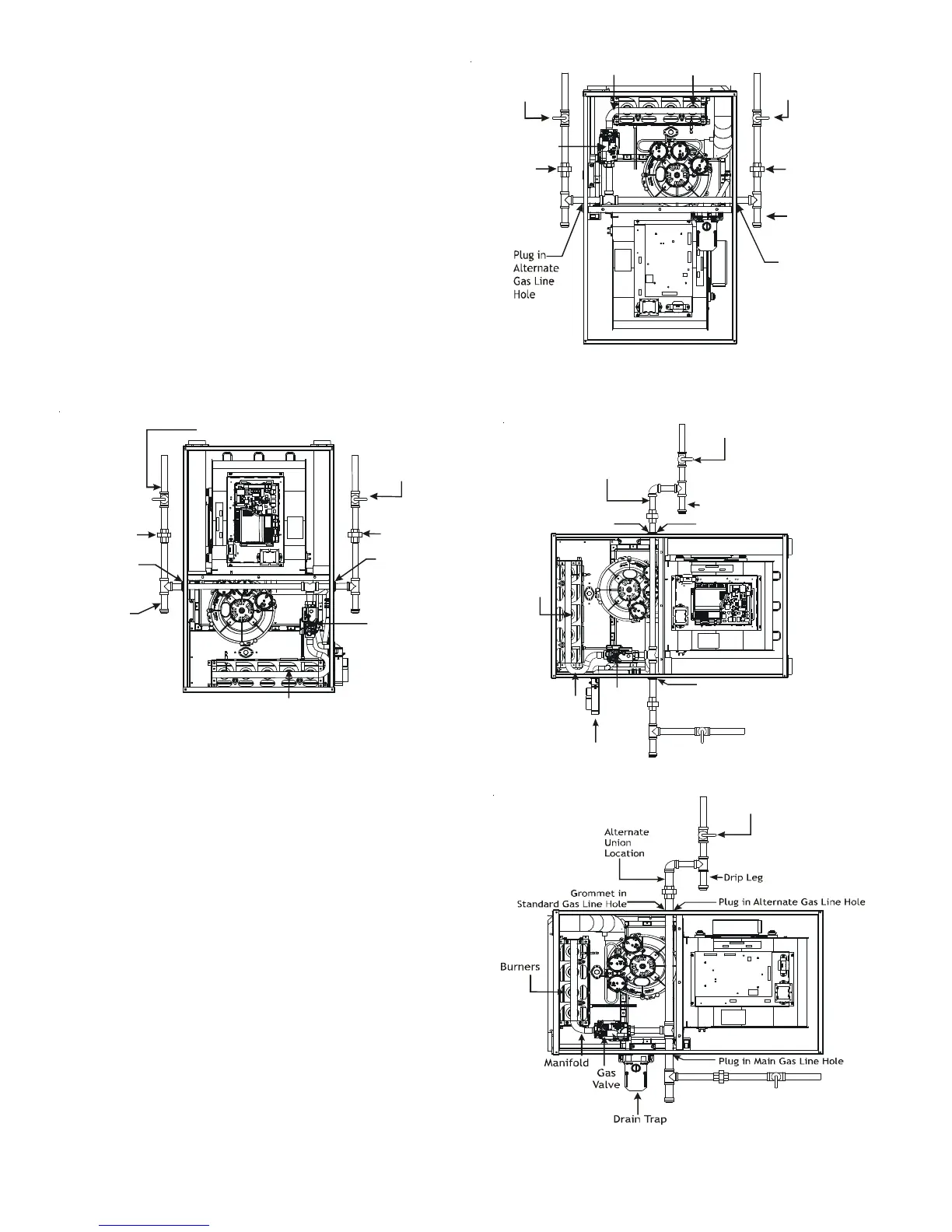
Drip Leg
Plug in Main Gas Line Hole
Alternate
Union
Location
Manual Shut Off Valve
(upstream from
ground joint pipe union)
Gas
Valve
Burners
Drain Trap
Manifold
Plug in Alternate Gas Line Hole
Grommet in
Standard Gas Line Hole
UPFLOW - HORIZONTAL LEFT
Figure 38
Manual Shut Off Valve
(upstream from
ground joint
pipe union)
COUNTERFLOW - HORIZONTAL RIGHT
Figure 39
Gas Piping Connections