36
1. Turn OFF gas to furnace at the manual gas shutoff valve external
to the furnace.
2. Connect a calibrated water manometer (or appropriate gas
pressure gauge) at either the gas valve inlet pressure tap or
the gas piping drip leg. See Honeywell VR9205 gas valve figure
or White-Rodgers 36J54 gas valve figure for location of inlet
pressure tap.
NOTE: If measuring gas pressure at the drip leg or Honeywell VR9205
gas valve, a field-supplied hose barb fitting must be installed prior
to making the hose connection. If using the inlet pressure tap on
the White-Rodgers 36J54 gas valve, then use the 36G/J Valve
Pressure Check Kit, Part No. 0151K00000S.
3. Turn ON the gas supply and operate the furnace and all other gas
consuming appliances on the same gas supply line.
4. Measure furnace gas supply pressure with burners firing. Supply
pressure must be within the range specified in the Inlet Gas Supply
Pressure table.
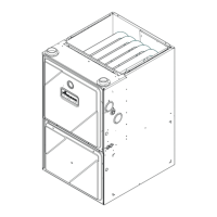
White-Rodgers Model 36J54 (Two-Stage)
Figure 45A
Inlet
Pressure
Boss
Low Fire
Regulator
Adjust
M
a
n
o
m
e
t
e
r
M
a
n
o
m
e
t
e
r
H
o
s
e
High Fire Regulator
Adjust
Regulator
Vent
Outlet
Pressure Boss
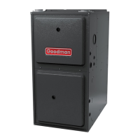
Open t
Atmosphere
O
n
/
O
f
f
S
w
i
t
c
h
H
i
g
h
F
i
r
e
C
o
i
l
T
e
r
m
i
n
a
l
(
H
I
)
C
o
a
x
i
a
l
C
o
i
l
T
e
r
m
i
n
a
l
(
M
)
Common
Terminal(C)
White-Rodgers Model 36J54 Connected to Manometer
Figure 45B
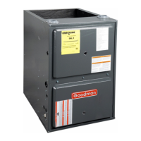
Gas Valve On/Off
Selector Switch
Regulator
Vent
Low Fire
Regulator
Adjust
High Fire
Regulator
Adjust
Honeywell Model VR9205 (Two-Stage)
Figure 46A
i
M
a
n
o
m
e
t
e
r
M
a
n
o
m
e
t
e
r
H
o
s
e
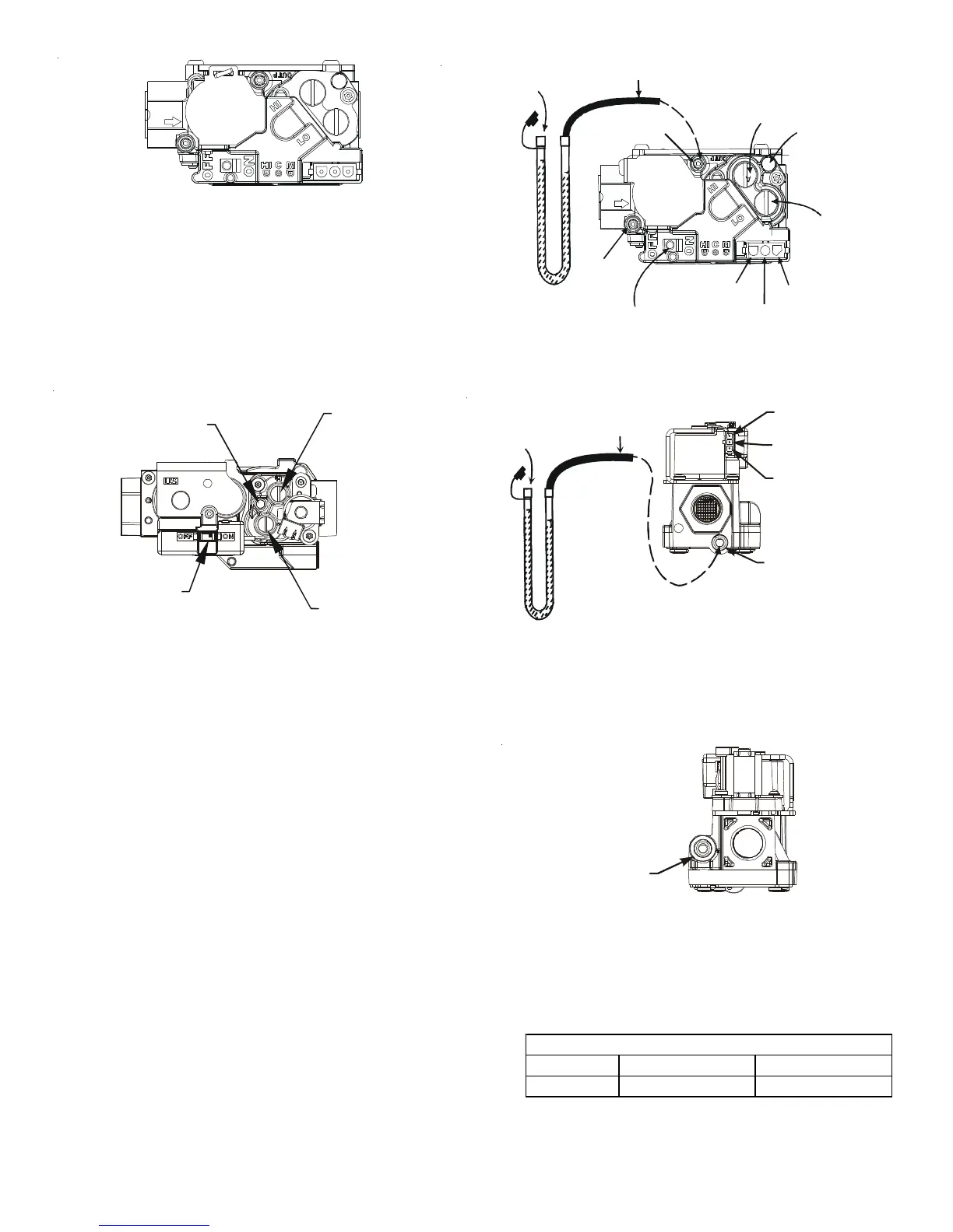
Common
Terminal
C
High Fire Coil
Terminal (HI)
Low Fire Coil
Terminal (LO)
Inlet Pressure Tap
1/8 NPT
O
p
e
n
t
o
A
t
m
o
s
p
h
e
r
e
Honeywell Model VR9205 Connected to Manometer
Figure 46B
Outlet Pressure Tap
1/8 NPT
Figure 46C
Natural Gas Minimum: 4.5" w.c. Maximum: 10.0" w.c.
Propane Gas Minimum: 11.0" w.c. Maximum: 13.0" w.c.
INLET GAS SUPPLY PRESSURE